ARMING A BREADBOARD — EVERYONE SHOULD PROGRAM AN ARM

I’m always a little surprised that we don’t see more ARM-based projects. Of course, we do see some, but the volume isn’t what I’d expect given that low-level ARM chips are cheap, capable, low power, and readily available. Having a 32-bit processor with lots of memory running at 40 or 50 MIPS is a game changer compared to, say, a traditional Arduino (and, yes, the Arduino Due and Zero are ARM-based, so you can still stay with Arduino, if that’s what you want).
A few things might inhibit an Arduino, AVR, or PIC user from making the leap. For one thing, most ARM chips use 3.3V I/O instead of the traditional 5V levels (there are exceptions, like the Kinetis E). There was a time when the toolchain was difficult to set up, although this is largely not a problem anymore. But perhaps the largest hurdle is that most of the chips are surface mount devices.
Of course, builders today are getting pretty used to surface mount devices and you can also get evaluation boards pretty cheaply, too. But in some situations–for example, in classrooms–it is very attractive to have a chip that is directly mountable on a common breadboard. Even if you don’t mind using a development board, you may want to use the IC directly in a final version of a project and some people still prefer working with through hole components.
THE 28 PIN SOLUTION
One solution that addresses most, if not all, of these concerns is the LPC1114FN28 processor. Unlike most other ARM processors, this one comes in a 28 pin DIP package and works great on a breadboard. It does require 3.3V, but it is 5V tolerant on digital inputs (and, of course, a 3.3V output is usually fine for driving a 5V input). The chip will work with mbed or other ARM tools and after prototyping, you can always move to a surface mount device for production, if you like. Even if you are buying just one, you should be able to find the device for under $6.
I recently wanted some breadboard setups for students. I did end up make a simple PCB that plugs into a breadboard, but looking back the simple circuit would have worked just as well placed directly on a breadboard. Here’s what you need:
- An LPC1114FN28
- A 3.3V power supply
- A 3.3V or 5V USB to serial cable or adapter
- One or two 220 ohm resistors (not absolutely necessary)
- An LED and suitable resistor (optional)
- Two 0.1uF capacitors (not absolutely necessary)
If you have a USB cable that puts out 3.3V, you can probably drive the chip directly with that. Otherwise, you can use an LD1117-3.3 or an LM7833. A bench supply or one of those cheap power supplies that plugs into a breadboard will work too. Just remember, the chip needs between 1.8V and 3.6V to operate.
BUILDING THE HARDWARE
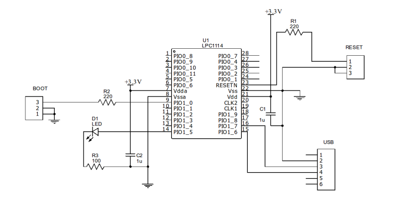
The circuit is so simple, you almost don’t need a schematic. Here’s one anyway:
One reason that this works so well is the chip has a built-in serial bootloader. If you short the PIO0_1 pin to ground and reset the chip, you can easily upload a program to the device. You could probably get away with just shorting both pins to ground (they are internally pulled up). However, I like to put a small (220 ohm) resistor in series in case software is driving the pin as an output for some reason.
Of course, the jumpers (BOOT and RESET) and connectors in the schematic can just be breadboard wires if you don’t want to mount actual pins. The USB “connector” assumes that pin 2 is ground, pin 3 is the PC’s receiver and pin 4 is the transmit (that is, the LPC1114 talks on 16 and listens on pin 15). If that doesn’t match your cable or RS232 converter, change it as needed.
You may also want to adjust the value of the resistor depending on your LED, but you aren’t making a flashlight, so any value that will get a visible glow ought to be fine (or, omit it completely if you don’t want to blink an LED). If you are a real minimalist, you could dump the 220 ohm resistors, too. The capacitors help decouple your power supply, but breadboards have a good bit of capacitance already and if you have a clean supply, you might not need those either.
So if you have a breadboard and a USB to serial adapter, you could build the bare bones version of this for about $6 and maybe break the bank at $15 if you had to buy everything. Of course, if you have another ARM programmer/debugger that you want to use, that could be wired up instead of the USB cable. But I’m guessing if you have that kind of hardware, you’ve already solved your breadboarding problem.
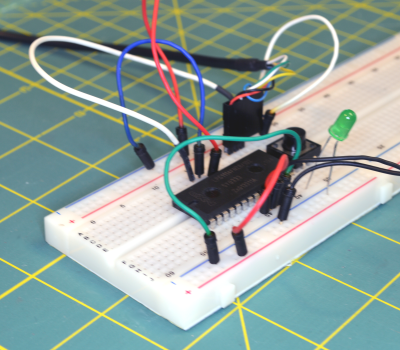
 Here’s my (almost) bare bones version:
Not pretty, but effective. I used a switch for the reset and just a wire for the boot jumper. The LED has an internal 5V dropping resistor, but works fine at 3.3V (and I dropped the other two resistors and the capacitors). To work through the software example below, you’ll either need another LED connected to pin 1, or you can just lift up the connection on the breadboard and repurpose the LED. Be aware though: The mbed code assumes you have an LED connected to pin 14 and will blink it if it finds run time errors. If you move the LED you could have an error and won’t get an indication.
SOFTWARE
You can use any ARM tool chain that can generate code for the LPC1114. There are plenty to choose from, but I’m going to assume you are just getting started, so let’s use the mbed web site. I’ve covered how to program using mbed before, and you might want to check out the video below for that walk through.
Here’s a quick summary of the steps you’ll need to take:
- Go to http://developer.mbed.org
- Create an account if necessary and log in
- Click on Platforms and find LPC1114FN28 (or go directly to the page)
- Click Add to Your mbed Compiler–if you see a button that says Remove, you’ve already done this
- Now head to the project page and import the project
- Compile the project and download the BIN file
Once you have the BIN file you’ll need to upload the program via your serial port. I’m going to use a utility called lpc21isp to do that. You can usually find this in your Linux repository, and there is a Windows version available, too. If you just hate the command line, you can always use FlashMagic or the official NXP Windows downloader. There are some GUI front ends for lpc21isp, too, but it is simple enough to use the command line.
The file you’ll download from the mbed website will be named HaD1114Demo_LPC1114.bin unless you changed it (I’ll assume it is in directory /tmp). You also need to know the name of your serial port (e.g., COM1 or /dev/ttyUSB8). The last thing you need to know is roughly what clock frequency the CPU is using. In our case it is 48MHz. Here’s the command line:
lpc21isp -verify -bin /tmp/HaD1114Demo_LPC1114.bin /dev/ttyUSB8 115200 48000
You want to engage the boot jumper and reset the chip either right before or right after executing that command line. The 115200 sets the baud rate and the 48000 is required so the software can sync with the bootloader.
Once you get a successful download, lpc21isp will tell you it is launching the new code. Don’t believe it — It isn’t doing anything yet. You’ll need to disengage the boot jumper and then reset the CPU again. If you prefer to do just a blinking LED, start a new project and that’s one of the boilerplate examples you can use in a new project.
INSIDE THE CODE
The code is simple. Just like the Arduino has a lot of helper library routines, mbed provides most of what you need to drive the devices on the CPU. There’s also an active community of shared libraries for external devices and example code. Here’s the simple code used for the demo:
|
1
2
3
4
5
6
7
8
9
10
11
12
13
14
15
16
|
#include "mbed.h"PwmOut myled(dp1);int main() { int i,j; while(1) { for (j=0;j<2;j++) for (i=0;i<1000;i+=10) { float pwm=i/1000.0; myled=j?1.0-pwm:pwm; wait(0.01); } }} |
The mbed library frequently makes use of floating point numbers. In the example code, the PWM range is from 0.0 to 1.0. The wait call uses seconds, so 0.01 is 10 milliseconds (there is a wait call that takes a millisecond value, by the way).
The j loop keeps track of even or odd passes so the PWM gets reversed on alternate passes. When j is zero, the PWM goes from 0 to 1.0. When j is not zero, the steps go from 1.0 down to 0. Each pass requires 100 steps (0 to 1000, counting by 10s) so the total time per pass is about 100 times 10 millisecond, or one second.
WHAT’S NEXT?
The mbed library is one place to start, and you can read its documentation online. If you are tied to the Arduino library, there is a port on Github (although I haven’t tried it). However, you can step up to bigger tools and even debugging when you are ready (there’s a good set of examples on Digikey’s eewiki, or you can keep using mbedwith your own IDE and debugger). If you want a quick rapid prototyping arrangement, this set up will easily run a pretty nice Forth, too. And if you are concerned that this isn’t really a hack, you could always chop the chip down to size literally (although we don’t recommend it).
