Quantcast
Channel: 懒得折腾
Viewing all 764 articles
Browse latest View live

Reading Weather Data with Software-Defined Radio

$
0
0

Reading Weather Data with Software-Defined Radio

Waverider – Software Defined Radio

By

Konstantin Agouros

Armed with a US$ 20 hunk of hardware and a free software-defined radio tool, we start the hunt for radio-transmitted data from a weather station.

Weather stations with transmitters (Figure 1) are used in many households today, including my own. The small transmitter, in this case, is on the window sill, measuring weather data such as temperature, air pressure, and humidity and transmitting the results digitally to a base station, which then displays them. However, a base station is not even necessary for receiving the data. With a little passion for tinkering, and the help of software-defined radio, I can receive, read, and even produce this wireless data with my own computer.

Figure 1: Communication between a commercial weather station (left) and the associated sensor (right) can be evaluated with SDR

Software-defined radio (SDR) picks up electromagnetic waves almost directly at the antenna and uses software to process them. In the simplest case, an SDR-receiver consists of an antenna and an analog-to-digital converter plus software. Depending on the device, it can thus scan a very large frequency range. Applications for implementing SDR include GNU Radio, GNU Radio Companion, or Gqrx.

The software does the majority of the work, so your soldering iron can stay safely in the cabinet. You only need to find the right hardware, which costs only a few dollars, as well as an editor to process the digitized radio data on your computer.

The Hardware

The first step is to find the right reception hardware. Although specially developed hardware is quite expensive, DVB-T sticks at around US$ 20 offer a very convenient entry point into SDR, as long as they use a Realtek chipset (RTL2832U). The whole thing operates under the RTL SDR umbrella and relies on Librtlsdr library.

A look at my weather station shows that it receives data on 868MHz. Online sources list variouschipsets and the frequency ranges they cover. On the recommendation of a colleague, I bought a Terratec Cinergy T Stick RC with Elonics chipset that covers the largest frequency range of the listed DVB-T receivers – and that includes the weather sensor’s frequency. The hardware cost me US$ 25; a rod antenna is included.

Software

The basis for the installation was a netbook with Mint 15; the GNU Radio Framework helped to analyze the received radio signals. This kind of kit even includes a graphical editor and supports raw data signal processing (optionally also in realtime) to create a target format with the help of various filters. The software automatically generates Python code that processes the data.

To use the DVB-T stick as a receiver, I first need the RTL SDR package. Typing:

git clone git://git.osmocom.org/rtl-sdr.git

installs RTL SDR on my computer. Gentoo and Arch Linux include prebuilt packages; on Ubuntu, you can install the software from a PPA (see the “GNU Radio from a PPA” section).

Building the software from the source works with cmake, but there’s a catch: RTL-SDR uses the libusb library to communicate with the stick. However, when certain drivers are loaded, the software fails to correctly talk to the stick. My Mint system loaded the modules from Listing 1. Listing 2 shows a guide from the website [1] for building the software from the source code.

Listing 1: lsmod | head 7

e4000              12862  1
rtl2832            13312  1
dvb_usb_rtl28xxu   18737  0
rtl2830            13511  1 dvb_usb_rtl28xxu
dvb_usb_v2         22916  1 dvb_usb_rtl28xxu
dvb_core           90402  3 rtl2830,rtl2832,dvb_usb_v2
rc_core            21266  3 dvb_usb_rtl28xxu,dvb_usb_v2

Listing 2: Compiling rtl-sdr

cd rtl-sdr/
mkdir build
cd build
cmake ../
make
sudo make install
sudo ldconfig

Gnu Radio from a PPA

Before plugging in the hardware, Ubuntu users need to create a udev file. To this end, run lsusb to determine the vendor and product ID of your DVB-T stick and issue the following command as root:

echo 'SUBSYSTEM=="usb", ATTRS{idVendor}=="Vendor_ID", \
      ATTRS{idProduct}=="Product_ID", GROUP="adm", MODE="0666", \
      SYMLINK+="rtl_sdr"' > /etc/udev/rules.d/20.rtlsdr.rules

This command writes a new rule for udev that references the DVB-T stick. You also need to restart udev as root before connecting the stick:

service udev restart

Ubuntu users install the Debian packages of GNU Radio and Gqrx from a PPA:

sudo add-apt-repository ppa:gqrx/snapshots
sudo apt-get update
sudo apt-get install gqrx gnuradio

Testing, Testing, 123 …

To prevent the modules from loading, the udev rules need to be modified. To do this, I had to expand the cmake call adding the -DINSTALL_UDEV_RULES = ON parameter and then still issue the following command:

sudo make install-udev-rules

after doing so. You can now read the hardware functions as follows

rtl_test -t

to find out about, for example, which frequency range the DVB-T stick covers. Another practical test would be to receive a local radio station:

rtl_fm -f 98.5M -W -s 200000 -r 48000 - | aplay -r 48k -f S16_LE

The demodulator rtl_fm takes 200,000 samples per second on a frequency of 98.5MHz (the frequency of a radio transmitter). The aplay command plays the data stream on stdout at a rate of 48kHz. Because the raw audio file does not contain header information, aplay reads the data at this rate and encodes it with 16-bit in little-endian format.

Analysis

To find interesting signals in the ether, a spot of listening is now in order. The command I used previously for listening to the radio delivers noise on other frequencies if nothing is transmitting. Digital signals sound different from noise and thus provide input for further analysis. (Keep in mind that some jurisdictions limit the frequency ranges authorized for casual listening and might prohibit intercepting police and emergency broadcasts.)

To scan larger frequency ranges, you will need a program like Gqrx, which offers a practical front end, visually processing the data to create line and waterfall charts (Figure 2).

Figure 2: Representing frequency data with Gqrx.

And Now for the Weather

Because the right frequency is printed on my weather station, luckily, there was no need to search. When I set the frequency to 868MHz, I could hear pops every few seconds; I recorded and then analyzed these transmissions with the Audacity audio editor. Importing the data resulted in the test image from Figure 3.

Figure 3: Zooming in on one of the peaks in the data with Audacity revealed the chart shown in Figure 4.
Figure 4: Use a script to decode the bit pattern shown in Audacity.

In fact, the magnified view revealed a pattern. I now had to decode the signal to read the temperature and humidity. An Internet search showed that someone had already done this work.

Christophe Jacquet’s Pydemod package assumes a 16-bit preamble, consisting of 1010101010101010. Following this, a sensor (see the Pydemod website) sends 17200 baud signal using on-off keying. For a rising curve, as shown of Figure 5, 1 is transmitted, while a 0 is sent for a drop. To discover whether the values are rising, evaluate the ratio of the numerical values of the samples compared with the baud rate.

Figure 5: Finally, the correctly demodulated signal.

My initial tests, which evaluated data from rtl_fm using decode_tfa.py, remained inconclusive. Unfortunately, Christophe’s records did not indicate how he called rtl_fm to obtain the raw data for the analysis. Also, the screenshot of the received data in his blog looked very different from mine.

Luckily, Christophe helped me out and expanded his script so that it also works with the data from my weather sensor. We discovered the following problems:

  • My samples were created with the wrong modulation method. The transmitter modulates the amplitude not the frequency. It is therefore necessary to run rtl_fm with the -M parameter.
  • My transmitter sends the data at 9600 instead of 17200 baud.
  • The data preamble was not 1010101010101010, but 101010101010101010101010, so it was actually 24 bits instead of 16.

I found another difference between my test system and Christophe’s data: His radio reception system, a FUNcube dongle, supplied the data in big-endian format; the DVB-T stick used in my test, however, used little-endian format. Christophe had to adjust the section code that transforms the raw samples to numbers for further processing.

The temperature coding remained the same in both scenarios. Three nibbles (4 bits) encode a temperature digit in BCD (Binary Coded Decimal), where the third digit shows tenths of a degree. My temperature sensor added 40 to the temperature reading, presumably to handle degrees below zero. The next 8 bits then encode the humidity.

The first version of the script also assumed that the input was a WAV file that contained exactly the bits with the information and no noise. The script, which Christophe has now significantly revised and expanded, includes a few more new features, such as:

  • It detects a data peak when the numerical value of the sample exceeds a limit. This currently limit is set to 4000, but you can change it – depending on the transmitter output.
  • The data can also be present in raw mode, that is, without a WAV header, but at the moment, the rate must be 160,000 per second.
  • The length of the preamble is managed by a separate parameter.
  • You can adjust the baud rate for the data transfer.

The following call generates a stream of temperature measurements:

rtl_fm -M -f 868.4M -s 160k - | python decode_tfa.py --raw - --bitrate 9600 --synclen 24

Listing 3 shows the output from the command. From time to time, the measurement data is faulty. You can detect a problem because a checksum is included, and its expected value and determined value are output. If the expected and determined values deviate from each other, a measurement error has occurred. Extreme temperature jumps are actually impossible; however, two measurements can differ by more than 1 degree Celsius.

Listing 3: Output from rtl_fm

Found 1 device(s):
  0:  Realtek, RTL2838UHIDIR, SN: 00000001
 
Using device 0: Terratec Cinergy T Stick RC (Rev.3)
Found Elonics E4000 tuner
Bitrate: 9600, synclen: 24, framelen: 80
Using frame duration 1600.0 samples
Squelch at 2200, should be slightly greater than usual max; use --squelch to change
Oversampling input by: 7x.
Oversampling output by: 1x.
Buffer size: 7.31ms
Tuned to 868679999 Hz.
Sampling at 1120000 Hz.
Output at 160000 Hz.
Exact sample rate is: 1120000.035604 Hz
Tuner gain set to automatic.
Min: 0 - Mean: 273.97845 - Max: 1224
---------------------------------------
Frame: size 98 bits, contents \
   10101010101010101010101000111101110101000000000000000000000000000000000000000000000000000000000000, \
   framelen=80
Frame hex contents: AA AA AA 3D D4 00 00 00 00 00
CRC: calculated=00, received=00
Temperature: -40.0 C -- Humidity: 0 %
---------------------------------------
Min: 0 - Mean: 270.3753 - Max: 1260
---------------------------------------
Frame: size 96 bits, contents \
   101010101010101010101010001011011101010010010001110001000110001001001001011001010000000000000000, \
   framelen=80
Frame hex contents: AA AA AA 2D D4 91 C4 62 49 65
CRC: calculated=65, received=65
Temperature: 6.2 C -- Humidity: 73 %
---------------------------------------

In practical tests, we found that the antenna should not be too far from the receiver. Even at a distance of 5 meters, the peak value dropped significantly in my tests. If the value is too close to the noise, the script cannot detect the beginning of the data.

The Python script outputs the minimum, maximum, and average values at runtime. However, in a practice test, it happened again and again that the deflection returned by the stick was too weak. This problem might be due to automatic signal amplification. You can either fix the value using the -g value parameter or unplug the stick and plug it back into the computer.

Easy Weather

With very little financial outlay and, ultimately, very little software, you can solve the problem of reading data from a weather station and converting into a digitally processable format. The base station of my test device also receives data with weather and pollen forecasts via the legacy pager network. You can receive and decode this pager data using the multimode-ng tool. The pager data is sent in plain text, but the string encoding is still undocumented.

A big thank you goes to Christophe Jacquet for the modifications to his script that allowed for real-time streaming.

Author

Konstantin Agouros works for n.runs AG as a consultant for network security. His focus is on cellular networks. His book DNS/DHCP is published by Open Source Press.


Reverse Engineer Wireless Temperature / Humidity / Rain Sensors

$
0
0

In this and the next two three blog posts (Part 2, Part 3, and Part 4), I will describe how I reverse engineered a few off-the-shelf wireless temperature, humidity, and rain sensors, and used an Arduino (Update: RPi is also supported now!) to listen to and decode the sensor data. This has been a really fun journey and I will document the process as thoroughly as I can. Because there are lots of details, I don’t want to jam everything into a single post, so I have split the whole story into three posts. The Arduino and RPi programs are provided at the end of each post.

Introduction

The first question to ask is always: why am I doing this? Well, for good reasons: these off-the-shelf sensors are cheap, well-built, outdoor-proof, battery-driven and power efficient. If your project needs local weather data and you don’t want to spend time building your own transmitter units (which would bring up a whole bunch of engineering issues), these cheap sensors are the way to go. My original plan was to make use of the sensor data for sprinkler control systems. I actually set this as my next challenge to tackle in a blog post I wrote two years ago. It’s a shame that I lost track of it since then. But hey, two years later, I finally finished it. Better late than never!

Here are the three sensors that I gathered and will use as examples in the following. They all work in the 433MHzfrequency band.

Disclaimer: I am not associated with Acu-Rite in any ways, I just picked these sensors because they are common in retail stores.

IMG_0040IMG_0041

Preparation

The tools involved are quite simple: I used an Arduino and a 433MHz receiver. You should use thesuperheterodyne type of receiver as it has very good signal-to-noise-ratio. The super-regenerative type is too noisy and will only work in short range.

Also, to obtain an initial waveform in order to bootstrap the process, I used a RF sniffing circuit from my previous blog post (about interfacing with remote power sockets), a PC with line-in port, a 3.5mm audio cable, and the free Audacity software. If you don’t have a PC with line-in port (most laptops these days don’t have), you can buy aUSB sound card which has line-in port.

IMG_0052IMG_0051


Wireless Temperature Sensor

Raw Waveform. The temperature sensor is the simplest, so let’s take it down first. What I have at hand is anAcu-Rite 00782W3 indoor/outdoor temperature sensor. The package includes a receiver display unit, and a transmitter which sends a temperature reading every 1 to 2 minutes. Pop in the battery, power on the RF sniffing circuit, and launch the Audacity recording software, I got a waveform like the one shown on the right image below.

IMG_0043temp_sensor_waveform

By carefully looking at the waveform, I found the following patterns:

  • Each transmission consists of 8 repetitions of the same signal.
  • Every two repetitions are separated by a constant low sync signal that’s roughly 400 samples (in Audacity you can select a region and see the sample count). Given that the sampling rate is 44.1kHz, this is roughly 9.0ms (400 / 44.1 = 9.07).
  • The bit patterns are pretty clear: logic 1 is a constant low of about 180 samples (4.1ms), and logic 0 is a constant low of about 95 samples (2.1ms). Every two bit is separated by a constant high of about 24 samples (0.54ms).

arduino
Given the patterns, I then manually wrote down entire sequence of bits. For example, the image above shows a signal that’s:

11100110 10000000 11111010 01001011

I grouped them into bits of 8 so it’s easy to see the byte values. I also recorded the reference temperature displayed on the receiver unit at the time of capture, which is 77 degree Fahrenheit. At this point we don’t know yet how the bits are encoded (i.e. how they translate to 77). None of the bytes is directly equal to 77. But this is ok — if it was that easy, it wouldn’t have been fun any more :)

Create Temperature Variations. In the next step, I will create temperature variations so I can get a lot of different signals and reference readings. By checking how the signal changes, hopefully I can decipher the coding pattern. How do I vary the temperature? Simple: use a hair blower to increase the temperature, and throw the sensor into a fridge to decrease the temperature.

But I am not in a hurry to do that just yet — manually translating the waveform into bits is very tedious, and I worry that if I make a mistake that can compromise the analysis. So I need a way to automate the signal capturing process. Since I already know the signal timings, I can create an Arduino program to automatically translate the waveform into bits. This will make the capturing process a lot faster.

An Arduino Program for Bits Conversion. To get started, I connected the VCC, GND, and DATA pins of the RF receiver to Arduino’s 5V, GND, and D3 (interrupt 1). Then I wrote an interrupt handler to process the captured signal and convert it to bits. Earlier I’ve studied the RCSwitch library, which gave me a good idea of implementation.

Technically, the interrupt function is triggered every time the signal changes from high to low (falling edge) or low to high (rising edge). A ring buffer is used to track the timing between every two triggers. It then checks the timing to see if a sync signal (roughly 9.0ms) is present. Because the signal may still be noisy the first time the sync signal is received, we will wait till the second or third time it’s received to actually do the bits conversion.

Collect and Analyze Data. Now let the fun begin. With the Arduino program, I gathered a lot of data under various temperatures. Make sure to also gather some low temperature reading by putting the sensor in a fridge: I was surprised that the signal can actually go through a fridge door! Here is a selected list. The number at the end of each line is the reference temperature value shown on the display receiver.

10001011 10000001 00111110 00111101 (89°F)
10001011 10000000 11100100 01010001 (73°F)
10001011 10000000 10101101 00011011 (63°F)
10001011 10000000 00000111 00001010 (33°F)
10001011 10000000 00000001 01010000 (32°F)
10001011 10001111 11111011 00010111 (31°F)
10001011 10001111 11100010 10111010 (26°F)
10001011 10001111 11001011 10100101 (22°F)
10001011 10001111 01111100 10011010 ( 8°F)

Now the coding pattern is a lot more clear. The first byte is always the same, so it’s probably a signature or channel byte. This is used to avoid interference among multiple transmitters. Note that this byte is different from the one I manually wrote down, so I suspect the transmitter changes the signature every time it’s powered on. The second and third bytes show a clear trend as the temperature goes down. The last byte has no clear trend. It’s possibly some sort of CRC checking byte.

So how do the middle two bytes translate to the temperature values? Well, if you look at the 32°F line: the middle two bytes are very close to 0 (ignoring the leading 1). Since 32°F is roughly 0°C (Celsius), is it possible that the middle two bytes give the temperature in Celsius? After converting the reference temperature values to Celsius, the puzzle is instantly solved (the arrow below points to the decimal value of 12 bits shown in blue):

10001011 10000001 00111110 00111101 (32°C) -> 318
10001011 10000000 11100100 01010001 (23°C) -> 228
10001011 10000000 10101101 00011011 (17°C) -> 173
10001011 10000000 00000111 00001010 ( 1°C) -> 7
10001011 10000000 00000001 01010000 ( 0°C) -> 1
10001011 10001111 11111011 00010111 (-1°C) -> -5 (two's complement)
10001011 10001111 11100010 10111010 (-3°C) -> -30 (two's complement)
10001011 10001111 11001011 10100101 (-5°C) -> -53 (two's complement)
10001011 10001111 01111100 10011010(-13°F) ->-132 (two's complement)

So the temperature, in Celsius, is given by the 12 bits (shown in blue), divided by 10, and rounded to the nearest integer. Aha, that’s it! Now I can modify the Arduino program to not only print out the bits, but also decode the signal and get the real temperature values displayed onto the serial monitor.

Update: the code is adapted to RPi as well, using wiringPi. The code below uses wiringPi GPIO 2 (P1.13) for data pin.

Note that the program uses pretty tight margins (1ms to 2ms) for screening the signal timings. Depending on the quality of your 433MHz RF receiver, you may have to increase the margin to improve error tolerance.

I did some quick testing by hanging the temperature sensor outside on a tree. Then I compared the temperature value reported on the serial monitor and the reference temperature displayed on the receiver unit. The two matches very well. Cool, mission accomplished! :)

IMG_0045IMG_0047IMG_0049

Summary of the Process
  • Use the RF sniffing circuit and Audacity to capture an example signal; examine the signal and estimate timing information.
  • Write an Arduino program to automatically capture signals and convert them into bits.
  • Collect a lot of data, record the bits and write down the reference temperatures.
  • Examine the changes in the bits as the reference temperature changes, identify those bits that matter, and reason about how they translate to the reference value.
  • Modify the Arduino program to decode the bits into temperature value.

    Continuing from Part 1, this is the second post about how I reverse engineered a few off-the-shelf wirelesstemperature, humidity, and rain sensors, and used an Arduino to listen to and decode the sensor data. Update: RPi is also supported now! Check the provided programs at the end of this post.

    Wireless Humidity / Temperature Sensor

    Raw Waveform. The second sensor to tackle is the Acu-Rite 00592W3 humidity / temperature sensor. This one transmits not only temperature but also humidity values. The display unit is a lot larger and looks cooler than the previous (temperature-only) one. Cool, time to get hands dirty. Following the same procedure as before, pop in the battery, power on the RF sniffing circuit, and launch the Audacity recording software, I got a waveform like the one shown on the right image below.

    IMG_0053humidity_sensor_waveform

    This looks a whole lot longer than before. But the patterns are still quite clear:

    • Each transmission consists of 3 repetitions of the same signal.
    • Every two repetitions are separated by a sync signal defined as a constant low of 2.25ms (about 100 samples @ 44.1kHz sample rate). This is followed by 4 squarewaves of roughly 1.2ms wavelength.
    • The bit patterns are also clear as there are only two types of patterns: logic 1 is defined by a constant high of 400us followed by a constant low of 225us; and logic 0 is defined by a constant high of 250us followed by a constant low of 400us.

    Given the timing data, I quickly modified the Arduino program to convert this signal into bits. The only changes are how the sync signal is detected, and how the bit 1 and 0’s are defined.

    Collect and Analyze Data. I collected a few groups of data under different humidity and temperature conditions, and recorded the reference values shown on th

    e display unit. Given my experience with the first temperature sensor, I set the display unit to show temperature in Celsius, to save myself the trouble of doing the conversion. Here is a selected list of the data:

    10010011 00000010 01000100 00100010 00001001 10111110 11000010 (21°C/34%)
    10010011 00000010 01000100 00100010 00001001 11000101 11001001 (22°C/34%)
    10010011 00000010 01000100 10100011 00001001 11011000 01011101 (24°C/35%)
    10010011 00000010 01000100 00100010 00001001 01100101 01101001 (25°C/34%)
    10010011 00000010 01000100 00100001 00001001 01101100 01101111 (26°C/33%)
    10010011 00000010 01000100 10100000 00001001 11110011 01110101 (26°C/32%)
    10010011 00000010 01000100 10100000 00001001 11111001 01111011 (27°C/32%)
    10010011 00000010 01000100 10011111 00001010 10000001 00000011 (28°C/31%)
    10010011 00000010 01000100 00011110 00001010 10010011 10010100 (29°C/30%)
    10010011 00000010 01000100 00010100 00001010 11001001 11000000 (35°C/20%)
    10010011 00000010 01000100 10010000 00001010 11010111 01001010 (36°C/16%)

    Again, I grouped the data into bits of 8 to make it easy to see the byte values. The first three bytes are the same. Those are probably the signature / channel ID; the fourth byte is clearly correlated with the humidity — if you pick two lines with the same humidity value, the fourth byte is always the same. On close examination, the lowest 7 bits of that byte converts exactly to the decimal value of the humidity. To make it clear, I picked out the fourth byte, and wrote them down together with the reference humidity below:
    0 0100010 (34%)
    0 0100010 (34%)
    1 0100011 (35%)
    0 0100010 (34%)
    0 0100001 (33%)
    1 0100000 (32%)
    1 0100000 (32%)
    1 0011111 (31%)
    0 0011110 (30%)
    0 0010100 (20%)
    1 0010000 (16%)

    Aha, one puzzle is now solved. Not sure what the leading bit is (this will be revealed later), but we can move on to the next puzzle — temperature. Clearly the temperature has to do with only the last three bytes. So let me re-list them below with the reference temperature:
    00001001 10111110 11000010 (21°C)
    00001001 11000101 11001001 (22°C)
    00001001 11011000 01011101 (24°C)
    00001001 01100101 01101001 (25°C)
    00001001 01101100 01101111 (26°C)
    00001001 11110011 01110101 (26°C)
    00001001 11111001 01111011 (27°C)
    00001010 10000001 00000011 (28°C)
    00001010 10010011 10010100 (29°C)
    00001010 11001001 11000000 (35°C)
    00001010 11010111 01001010 (36°C)

    Because the data was recorded as the temperature went up, the first byte is clearly showing the right trend: it goes up as the temperature rises. These are probably the most significant 4 bits. The next byte is not very clear at all: sometimes it goes up, sometimes it goes down. What’s happening here? The last byte is even more elusive: but given my experience with the first temperature sensor, this is probably some sort of error checking code, so let me put it aside for now.

    To figure out what’s happening with the second byte, I needed more data. Using my old friends hair blower and fridge, I recorded a larger set of data, and here they are:
    00000110 11101011 11011100 (-13°C)
    00000110 11111001 11110000 (-12°C)
    -------- -------- -------- --------
    10000111 00000000 01111000 (-11°C)
    10000111 00110101 10110010 (-6°C)
    10000111 11010001 01001110 (-3°C)
    10000111 11011011 01011000 (-2°C)
    10000111 01011111 11011100 (-1°C)
    10000111 01101111 11101101 ( 0°C)
    10000111 11111001 11111000 ( 1°C)
    -------- -------- -------- --------
    10001000 00000011 00000011 ( 2°C)
    10001000 00010100 10010011 ( 4°C)
    10001000 01000001 00111110 ( 8°C)
    10001000 11110011 11100100 (13°C)
    10001000 01111101 01101110 (14°C)
    -------- -------- -------- --------
    00001001 00000110 01111000 (15°C)
    00001001 00001111 10000001 (16°C)
    00001001 00100010 10010100 (18°C)
    00001001 11011110 01011111 (24°C)
    00001001 11111100 11111001 (27°C)
    -------- -------- -------- --------
    00001010 00000011 00000001 (28°C)
    00001010 00001111 00001101 (29°C)
    00001010 11010001 01000100 (36°C)
    00001010 01100110 11011001 (38°C)
    00001010 11111111 01110010 (40°C)
    -------- -------- -------- --------
    10001011 10001110 10000010 (42°C)
    10001011 00011101 00010001 (43°C)
    10001011 01010011 01000111 (49°C)
    10001011 01111000 01101100 (52°C)
    -------- -------- -------- --------
    00001100 10000001 11110110 (53°C)

    The second byte still doesn’t show any clear trend; but the first byte is still well behaved: it consistently increments as the temperature rises. That’s re-assuring. I then noticed something very interesting, and that’s why I used dotted lines to separate the data: each dotted line marks where the first byte increments by 1. If you look at the temperature where these changes occur, there is an interesting pattern: the change occurs roughly every 12 degree Celsius.

    From my experience with the first temperature sensor, I know that it’s likely the data reflects 10 times the Celsius, so that means the change occurs at about every 120. This is very close to 128. If this is the case, then the lowest bit of the first byte must be the 8-th bit of the actual data (that’s how one bit of increment corresponds to a change of 128), and thus there must be 7 least significant bits following it! Could that be from the second byte?

    After staring at the data for a while, I see a path now: if you put together the lowest 4 bits of the first byte and the lowest 7 bits of the second byte, into a 11-bit binary number, this number consistently rises with the temperature. Aha, let me wrote them down here:
    0110 1101011 (-13°C) -> 875 => -14.9
    0110 1111001 (-12°C) -> 889 => -13.5
    0111 0000000 (-11°C) -> 896 => -12.8
    0111 0110101 (-6°C) -> 949 => -7.5
    0111 1010001 (-3°C) -> 977 => -4.7
    0111 1011011 (-2°C) -> 987 => -3.7
    0111 1011111 (-1°C) -> 991 => -3.3
    0111 1101111 ( 0°C) -> 1007 => -1.7
    0111 1111001 ( 1°C) -> 1017 => -0.7
    1000 0000011 ( 2°C) -> 1027 => 0.3
    1000 0010100 ( 4°C) -> 1044 => 2
    1000 1000001 ( 8°C) -> 1089 => 6.5
    1000 1110011 (13°C) -> 1139 => 11.5
    1000 1111101 (14°C) -> 1149 => 12.5
    1001 0000110 (15°C) -> 1158 => 13.4
    1001 0001111 (16°C) -> 1167 => 14.3
    1001 0100010 (18°C) -> 1186 => 16.2
    1001 1011110 (24°C) -> 1246 => 22.2
    1001 1111100 (27°C) -> 1276 => 25.2
    1010 0000011 (28°C) -> 1283 => 25.9
    1010 0001111 (29°C) -> 1295 => 27.1
    1010 1010001 (36°C) -> 1361 => 33.7
    1010 1100110 (38°C) -> 1382 => 35.8
    1010 1111111 (40°C) -> 1407 => 38.3
    1011 0001110 (42°C) -> 1422 => 39.8
    1011 0011101 (43°C) -> 1437 => 41.3
    1011 1010011 (49°C) -> 1491 => 46.7
    1011 1111000 (52°C) -> 1528 => 50.4
    1100 0000001 (53°C) -> 1537 => 51.3

    The single arrow points to the decimal value of the 11-bit number. There is obviously an offset of 1024, so I subtracted the value by 1024 and then divided it by 10. The result is shown following the double arrow.

    Now we are almost done. If you compare the result with the reference temperature, there is still some difference, like a 1.6 to 1.9 degree constant shift. This is probably due to calibration. The shift seems consistent, so I picked 1.9 as an empirical number. Putting everything together, the temperature is calculated as: [(11-bit number – 1024) / 10 + 1.9] rounded to the nearest integer.

    Parity Checking Bit. At this point you have probably already figured out about the mysterious leading bit (which I ignored above). It is a parity bit — it shows if there are an odd or even number of 1’s in the remaining 7 bits. It’s the simplest form of error detection. Because the first temperature sensor I worked with did not have a parity bit, I didn’t think about it immediately. It’s only after I figured out about the temperature encoding scheme that I came to realize the leading bit must be used for error checking. Here is a summary of the encoding scheme:

    humidity_sensor_bitdecode

    At this point, the last byte is still a mystery — as I said, it’s likely some sort of CRC checking code. Perhaps the experts can shed some light here?

    Arduino Program and Validation. It’s now time for the final test. Here is the Arduino program that listens to the transmitter and displays the humidity / temperature value to the serial monitor.

    Update: the code is adapted to RPi as well, using wiringPi. The code below uses wiringPi GPIO 2 (P1.13) for data pin.

    The result matches the display unit quite well. Cool. Mission accomplished!

    IMG_0051IMG_0054

    Continue to Part 3 and Part 4, or Back to Part 1.

    Continuing from Part 1 and Part 2, this is the third and last post about how I reverse engineered a few off-the-shelf wireless temperature, humidity, and rain sensors, and used an Arduino to listen to and decode the sensor data. Update: RPi is also supported now! Check the provided programs at the end of this post.

    Wireless Rain Sensor

    Raw Waveform. There are several different wireless rain sensors on the market. My first target was an Acu-Rite 00875W rain gauge. I bought it two years ago and I don’t know if it’s still available now. This sensor turns out to be a huge pain. The main problem is that I can’t even register a consistent reading at 0 — every time I pop in the battery, I get a different signal that seems to have nothing to do with the previous readings. Also, the 0/1 bit patterns are completely unclear from the captured waveform — there are at least 4 or 5 different wavelengths. Here are two examples of the captured waveforms. They look nothing alike, even though both were captured right after the batteries are popped in and no rain has been detected.

    IMG_0055rain_sensor_waveform0

    After pulling my hair for a couple of days and finding no clue at all, I decided to give it up and try a different model. This time I bought an Acu-Rite 00899 wireless rain gauge. It’s probably worth explaining at first how the rain gauge works, because it’s quite a clever design. The outside of the transmitter unit looks like a bucket. Underneath the bucket is a plastic seesaw which swings left and right. Basically the rain water drains through the bucket hole onto the seesaw, and creates some motion to be detected.

    IMG_0056IMG_0057IMG_0058

    At the bottom of the assembly is the battery compartment. Remove some tiny screws, the transmitter circuit is finally revealed. At the center is a reed switch, which is normally open but will close if there is a magnet nearby. It is very sensitive to magnetism. So where is the magnet? It’s on the bottom of the seesaw. The way this works is quite neat: the seesaw swings left and right, every time the magnet passes by the reed switch, it triggers a click. By detecting how many clicks there are within a given time, we know how heavy the rain is. Clever!

    IMG_0059IMG_0060IMG_0061

    So let’s see if this rain gauge is easier to tackle. Following the same procedure as before, pop in the battery, power on the RF sniffing circuit, and launch the Audacity recording software, I got a waveform like the one shown in the image below.

    rain_gauge_waveform

    Cool, this looks a lot better. I also made sure every time I pop in the battery I get the same waveform. So what patterns do I see here?

    • Each transmission consists of 3 repetitions of the same signal.
    • Every two repetitions are separated by a sync signal defined as 4 squarewaves of roughly 1.2ms wavelength.
    • The bit patterns are: logic 1 is defined by a constant high of 400us followed by a constant low of 200us; and logic 0 is defined by a constant high of 225us followed by a constant low of 400us.

    The sync signal is actually very similar to the humidity/temperature sensor I described in the Part 2. The difference is that there is no 2.25ms constant low preceding the 4 squarewaves.

    Given the timing data, here is the Arduino program to convert this signal into bits:

    Collect and Analyze Data. The transmitter sends a signal every two minutes, so it’s quite annoying that I had to wait two minutes for every reading. To create variations in data, I simply move the seesaw manually. This way I can precisely control how many clicks occurred between two readings. Here is a list of readings I captured. The numbers in the parentheses are the number of clicks since last reading, and the total number of clicks since the program started.


    01110010 11111000 11110000 00000000 00000000 00000000 00000000 01011010 (0 / 0 total)
    01110010 11111000 11110000 00000000 00000000 00000000 10000001 11011011 (1 / 1 total)
    01110010 11111000 11110000 00000000 00000000 00000000 10000010 11011100 (1 / 2 total)
    01110010 11111000 11110000 00000000 00000000 00000000 00000011 01011101 (1 / 3 total)
    01110010 11111000 11110000 00000000 00000000 00000000 10000100 11011110 (1 / 4 total)
    01110010 11111000 11110000 00000000 00000000 00000000 10000111 11100001 (3 / 7 total)
    01110010 11111000 11110000 00000000 00000000 00000000 10001101 11100111 (6 / 13 total)

    The encoding scheme is quite obvious: the first three bytes are the signature / device ID; the next 4 bytes record the total number of clicks since the transmitter is powered on. The leading bit of each byte is a parity bit (thanks to the lesson I learned from Part 2!) The last byte is for error checking.

    This time I looked at the error checking byte more carefully, and noticed some interesting patterns. For example, everything else being the same, the change in its first bit matches the change of the first bit in the second to last byte. This suggest that perhaps the last byte is a parity byte — specifically, bit 0 is the parity of the first bits in all the preceding 7 bytes, and bit 1 is the parity of the second bit in all the preceding 7 bytes and so on. Just eyeballing the numbers, I believe this looks correct.

    I felt quite happy that I made the right choice to abandon the first rain gauge which proved to be too difficult to solve. Well, dodging the challenge is not generally recommended, but in this particular case, I have no regret :)

    Arduino Program and Validation. Here is the Arduino program that listens to the rain gauge and displays the number of clicks onto the serial monitor. The numbers have been validated with the display unit.

    Update: the code is adapted to RPi as well, using wiringPi. The code below uses wiringPi GPIO 2 (P1.13) for data pin.

    IMG_0051IMG_0063

    This concludes the three-part series. If you have comments / questions / suggestions, please feel free to leave them below. Thanks!

    At the Maker Faire this year I got lots of questions about soil moisture sensors, which I knew little about. So I started seriously researching the subject. I found a few different soil sensors, learned about their principles, and also learned about how to make my own. In this blog post, I will talk about a cheap wireless soil moisture sensor I found on Amazon.com for about $10, and how to use an Arduino or Raspberry Pi to decode the signal from the sensor, so you can use it directly in your own garden projects.

    IMG_0183

    What is this?
    A soil moisture sensor (or meter) measures the water content in soil. With it, you can easily tell when the soil needs more water or when it’s over-watered. The simplest soil sensor doesn’t even need battery. For example, thisRapitest Soil Meter, which I bought a few years ago, consists of simply a probe and a volt meter panel. The way it works is by using the Galvanic cell principle — essentially how a lemon battery or potato battery works. The probe is made of two electrodes of different metals. In the left picture below, the tip (dark silver color) is made of one type of metal (likely zinc), and the rest of the probe is made of another type of metal (likely copper, steel, or aluminum). When the probe is inserted into soil, it generates a small amount of voltage (typically a few hundred milli-volts to a couple of volts). The more water in the soil, the higher the generated voltage. This meter is pretty easy to use manually; but to automate the reading you need a microcontroller to read the value.

    IMG_0180IMG_0182

    Resistive Soil Moisture Sensor
    Another type of simple soil sensor is a resistive sensor (picture on the right above). It’s made of two exposed electrodes, and uses the fact that the more water the soil contains, the lower the resistance between the two electrodes. The resistance can be measured using a simple voltage dividier and an analog pin. While it’s very simple to construct, resistive sensors are not extremely reliable, because the exposed electrodes can degrade and get oxidized over time.

    Capacitive Soil Moisture Sensor
    Capativie soil sensors are also made of two electrodes, but insulated (i.e. not exposed). The two electrodes, together with the soil as a dielectric material, form a capacitor. The higher the water content, the higher the capacitance. So by measuring the capacitance, we can infer the water content in soil. There are many ways to measure capacitance, for example, by using the capacitor’s reactance to form a voltage divider, similar to the resistor counterpart. Another way is to create an RC oscillator where the frequency is determined by the capacitance. By counting the oscillation frequency, we can calculate the capacitance. You can also measure the capacitance by charging the capacitor and detecting the charge time. The faster it charges, the smaller the capacitance, and vice versa. The Chirp (picture below), which is an open-source capacitive soil sensor, works by sending a square wave to the RC filter, and detecting the peak voltage. The higher the capacitance, the lower the peak voltage. Capacitive sensors are not too difficult to make, and are more reliable than resistive ones, so they are quite popular.

    chirp

    More Complex Soil Sensors
    There are other, more complex soil sensors, such as Frequency Domain Reflectometry (FDR), Time Domain Reflectometry (TDR), and neutron sensors. These are more accurate but also will cost a fortunate to make.

    Wireless Soil Moisture Sensor
    Because soil sensor is usually left outdoors, it’s ideal to have it transmit signals wirelessly. In addition, because soil moisture can vary from spot to spot, it’s a probably good idea to use multiple sensors distributed at different locations to get a good average reading. Wireless would make it more convenient to set up multiple sensors.

    Recently I found this 433MHz wireless soil sensor from Amazon, for only $10, very cheap. It comes with a transmitter unit and a receiver display unit. The transmitter unit has a soil probe. The receiver unit has a LCD — it displays soil moisture level (10 bars) and additionally indoor / outdoor temperature. Let me open up the transmitter to see what’s inside:

    IMG_0177IMG_0178IMG_0179IMG_0181

    There is a soil probe, a 433MHz transmitter, a microcontroller at the center, a thermistor, and a SGM358 op-amp. Pretty straightforward. The soil probe looks quite similar to the battery-free soil meter probe that I mentioned above. So I am pretty sure this is not a resistive or capacitive probe, but rather a Galvanic probe. Again, the way it works is by outputting a variable voltage depending on the water content in soil. By checking the PCB traces, it looks like the op-amp is configured as a voltage follower, which allows the microcontroller to reliably read the voltage generated by the Galvanic probe.

    Now we understand the basic principle of the sensor, let’s take a look at the RF signal from the sensor. I’ve done quite a few similar experiments before, so I will just follow the same procedure as described in this post.

    Raw Waveform. To begin, I use a RF sniffing circuit to capture a raw waveform, which looks like this:

    soil_waveform

    Encoding. Each transmission consists of 8 repetitions. The above shows one repetition: it starts with a sync signal (9000us low); a logic 1 is a impulse (475us) high followed by a 4000us low; a logic 0 is the same impulse high followed by a 2000us low. So the above signal translates to:

    11110011 01100000 11111111 00111001 1111

    The signal encodes both temperature and soil humidity values. By varying temperature and soil moisture, and observing how the signals change, it’s pretty easy to figure out that the 12 bits colored blue correspond to temperature (10 times Celcius), and the 8 bits colored red corespond to the soil moisture value. The first 12 bits are device signature, which is quite typical in this type of wireless sensors; the last four bits are unclear, but likely some sort of parity checking bits for the preceding four bytes). So the above signal translates to 25.5°C and a soil moisture value of 57.

    The display unit shows soil moisture level in 10 bars — 1 to 3 bars are classifed as ‘dry’, 4 to 7 bars are classified as ‘damp’, and above 7 bars are classified as ‘wet’. How does this translate to the soil moisture value? Well empirically (from the data I observed) the dry-damp boundary is around 60, and damp-wet boundary is around 100.

    Arduino Program. I next wrote an Arduino program to listen to the sensor and display the soil moisture value and temperature to the serial monitor. For this you will need a 433MHz receiver, and the program below assumes the receiver’s data pin is connected to Arduino digital pin 3. Because the encoding scheme is very similar to a wireless temperature sensor that I’ve analyzed before, I took that program and made very minimal changes and it worked instantly.

    IMG_0051soil_display_arduino

    Raspberry Pi Program. By using the wiringPi library, the Arduino code can be easily adapted to Raspberry Pi. The following program uses wiringPi GPIO 2 (P1.13) for data pin.

    IMG_0185IMG_0184

    I haven’t done much tests about the transmission range. I’ve put the sensor at various locations on my lawn, and I’ve had no problem receiving signals inside the house. But my lawn is only a quarter acre in size, so it’s not a great test case.

    One thing I really liked about using off-the-shelf sensors is that they are cheap and have ready-made waterproof casing. That combined with an Arduino or RPi can enable a lot of home automation projects at low cost.

    New: continue to Part 4, wireless soil moisture sensor.


MegaStat – Second Gen Smart Thermostat – 3. 433Mhz Receiver

$
0
0

http://csb.idilks.com/2014/03/megastat-second-gen-smart-thermostat-3.html

MegaStat – Second Gen Smart Thermostat – 3. 433Mhz Receiver

433 Mhz Communication with Spark Core

We have successful communication from the PIC temperature monitors to the Spark Core using the Linx 433 Mhz module.  The first step is to solder the Linx module to some wires since this module is a 16-SMD package and will be hard to bread board.  With some solder wizardry I managed to get all the wires on the module and attach an antenna.

Linx 433 Mhz Receiver

On the transmitter modules (OOK Modulated) you will notice that in the code I have inverted the output going from the UART to the transmitter.  This is done because the normal marking state of a UART is logic 1 or high.  This marking state causes constant transmission.  This would not be good when we are trying to have many monitoring modules transmitting to the thermostat.  Therefore on the receiving end I also have to invert the output from the receiver going to the spark core.  This can be achieved with a transistor or there are some chips you can buy to do the inverting.

Inverter circuit hooked up to the receiver
So with the power (24VAC to 5VDC), Spark Core, and 433 Mhz receiver all together looks like the following photo.
I have updated the schematic but here is a snapshot pic of the schematic before adding more components.
The code for receiving the messages on the spark core is located here.  The code verifies the message a byte at a time.  This is done by XORing the previous byte.  It is a very simple but effective encoding method.  With this method I can verify the message as it is being received and I do not have to wait for the entire message and then check a checksum.  This message is composed in the following method.  Byte, XORed Byte, Byte, XORed Byte till the message is complete.  Our message is composed like so “!”, XOR, “T” (for temperature), XOR, device ID (0 – 255), XOR, Sign (“+” or “-” for the temperature reading), XOR, Degrees whole number, XOR, Degrees Decimal, XOR.  Here is a snapshot of the code that just verifies the message.
License is located here.

 byte RxMsg[11]; // Message from the sensors
 byte RxIdx = 0; // Index in message buffer
 void setup() {
   Serial.begin(9600);
   Serial1.begin(1200); // Init UART at 1200 baud
 }
 void loop() {
   // Loop while bytes are available
   while (Serial1.available()) {
     RxMsg[RxIdx] = Serial1.read(); // Read in first byte
     if (RxMsg[0] == 33) { // All messages start with "!"
       if ((RxIdx == 1 && RxMsg[1] != 222) || (RxIdx == 2 && RxMsg[2] != 84) || (RxIdx == 3 && RxMsg[3] != 171)) { // Verify First Part of Message is correct
         RxIdx = 0; // Message invalid start over
       } else if (RxIdx == 11) {
         bool goodMsg = true; // Made it this far, optimistic outcome
         RxIdx = 0; // Start message index over for next temp broadcast
         for (byte i=4; i <= 10 && goodMsg; i+=2) { // Validate the remaining bytes in the message
           if ((RxMsg[i] ^ 255) != RxMsg[(i + 1)]) {
             goodMsg = false;
             break;
           }
         }
         if (goodMsg) {
           // Create MonitorTmp, DeviceId, Sign, DegreesF, DecimalF
           //MonitorTemp Msg = MonitorTemp(RxMsg[4], RxMsg[6], RxMsg[8], RxMsg[10]);
           Serial.println("Code here to set processing temp");
         }
       } else {
         RxIdx++;
       }
     }
   }
 }
The above code was just to prove out we can send and receive a message via the USART and over the 433 Mhz module.
The temperature monitors are written in PICBasic Pro 2.5 using an 8 dip  PIC12F683 and the DS18B20 to measure the temperature.  Code for the temperature module can be found here.  Points to note in the temperature monitor code is that we use the software serial out with an inverted 1200 baud as our selection for transmitting the message.  The inversion takes in to account the UART normal marking state of logic 1 causing constant transmission.  On the code page you will also see a great example of one wire communiction with the temperature sensor and how to convert the temperature.  The temperature conversion calculation also considers if the result is in negative Celsius.  Many of the examples for converting temperature states that their calculation doesn’t work for negative results.  The code provided does not have this limitation.  Below is a snapshot of the temperature monitor code.  The code and design will change in the near future.  There are plans for adding a PIR sensor to detect if a room is occupied or not.  Occupied rooms ultimately will have more weight compared to other rooms.
License is located here. 
'**************************************************************** '* Name : Monitor.pbp * '* Author : Brian Dilks * '* Date : 10/11/2008 * '* Version : 1.0 * '* Notes : PIC12F683 * '* : * '**************************************************************** '_FCMEN_ON EQU H'3FFF' Fail Safe Clock Monitor '_FCMEN_OFF EQU H'37FF' '_IESO_ON EQU H'3FFF' Internal External Switchover bit '_IESO_OFF EQU H'3BFF' '_BOD_ON EQU H'3FFF' Brown Out '_BOD_NSLEEP EQU H'3EFF' Brown Out on, but not in sleep '_BOD_SBODEN EQU H'3DFF' Brown Out controlled by register '_BOD_OFF EQU H'3CFF' Brown Out off '_CPD_ON EQU H'3F7F' Data Code Protection '_CPD_OFF EQU H'3FFF' '_CP_ON EQU H'3FBF' Program Code Protection '_CP_OFF EQU H'3FFF' '_MCLRE_ON EQU H'3FFF' Reset Pin On '_MCLRE_OFF EQU H'3FDF' Reset Pin Off, Digital Input '_PWRTE_OFF EQU H'3FFF' '_PWRTE_ON EQU H'3FEF' Power Up Timer Enabled '_WDT_ON EQU H'3FFF' Watchdog Timer Enabled '_WDT_OFF EQU H'3FF7' '_LP_OSC EQU H'3FF8' '_XT_OSC EQU H'3FF9' XT OSC, OSC1 & OSC2 pins used '_HS_OSC EQU H'3FFA' '_EC_OSC EQU H'3FFB' '_INTRC_OSC_NOCLKOUT EQU H'3FFC' '_INTOSCIO EQU H'3FFC' '_INTRC_OSC_CLKOUT EQU H'3FFD' '_INTOSC EQU H'3FFD' '_EXTRC_OSC_NOCLKOUT EQU H'3FFE' '_EXTRCIO EQU H'3FFE' '_EXTRC_OSC_CLKOUT EQU H'3FFF' '_EXTRC EQU H'3FFF' @ __CONFIG _FCMEN_OFF & _IESO_OFF & _BOD_OFF & _CPD_OFF & _CP_OFF & _MCLRE_OFF & _PWRTE_ON & _WDT_ON & _XT_OSC DEFINE OSC 4 DEFINE CHAR_PACING 1000 ' WPU Disabled, Interrupt on rising edege, Internal Instruction Cycle Clock, inc low to high T0CK1, Prescaler on TMR0 ' TMR0 1:4, WDT 1:2 OPTION_REG = %11000001 INTCON = 0 ' All interrupts off ADCON0 = 0 ' A/D Converter disabled ANSEL = 0 WPU = 0' Weak pull ups disabled ' 76543210 CMCON0 = 000111 ' All digital i/o GPIO = 000000 TRISIO = 111100 ' MCLR pin - input, GPIO2 Input, <5:4> 1 for OSC1 & 2, GPIO<1:0> Output T1CON.0 = %0 ' Timer1 Off T2CON.2 = %0 ' Timer2 Off DeviceID CON 1 'OSC1 VAR GPIO.5 'OSC2 VAR GPIO.4 'MCLR VAR GPIO.3 pTempSensorIO VAR GPIO.2 pTxData VAR GPIO.1 pTxSTBY VAR GPIO.0 RandomVal VAR WORD ' Random value to drift some transmitters don't broadcast on top of each other. LastRandomVal VAR WORD ' Last value SleepSec VAR BYTE ' Amount of time to sleep TxMsg VAR BYTE[11] '-------------- Temp Sensor Variables ------------- Busy VAR BIT ' Busy Status-Bit LocalTempRaw VAR WORD ' RAW Temperature readings LocalTemp VAR WORD ' Temp in deg F LocalTempSign VAR LocalTempRaw.Bit11' Sign-Bit for +/- Temp. 1 = Below 0 deg C LocalTempCalc VAR BYTE ' Dummy for Div32 LocalTempDeg VAR BYTE ' Degrees LocalTempDec1 VAR BYTE ' Tenths of temp LocalFullTemp VAR WORD ' Final Temperature in full, tenths is ones position IsNegC VAR BIT ' Raw reading was negative '-------------- End Temp Sensor Variables ------------- '-------------- Pre-Loop Code --------------- LocalFullTemp = 0 RandomVal = 0 LastRandomVal = 0 TxMsg[0] = "!" TxMsg[1] = (TxMsg[0] ^ 255) TxMsg[2] = "T" TxMsg[3] = (TxMsg[2] ^ 255) TxMsg[4] = DeviceID TxMsg[5] = (TxMsg[4] ^ 255) SLEEP 10 MainLoop: OWOUT pTempSensorIO, 1, [$CC, $44]' Skip ROM search & do temp conversion Nag: OWIN pTempSensorIO, 4, [Busy] ' Read busy bit IF Busy = 0 THEN Nag ' busy keep looping OWOUT pTempSensorIO, 1, [$CC, $BE]' Skip ROM search & read scratchpad memory OWIN pTempSensorIO, 2, [LocalTempRaw.Lowbyte, LocalTempRaw.Highbyte]' Read two bytes IsNegC = LocalTempSign IF IsNegC = 1 THEN LocalTempRaw = (LocalTempRaw ^ 65535) + 1 LocalTempCalc = LocalTempRaw * 1125 LocalTemp = DIV32 100 TxMsg[6] = "+" IF IsNegC = 1 THEN IF LocalTemp > 3200 THEN TxMsg[6] = "-" LocalTemp = 3200 - LocalTemp ELSE LocalTemp = LocalTemp + 3200 ENDIF ' encode next char based off of last one TxMsg[7] = (TxMsg[6] ^ 255) LocalTempDeg = LocalTemp / 100 ' whole degrees LocalTempDec1 = LocalTemp DIG 1 ' Tenths IF LocalTemp DIG 0 >= 5 THEN ' Hundreths, round it LocalTempDec1 = LocalTempDec1 + 1 if LocalTempDec1 > 9 THEN ' Rounded up a degree LocalTempDeg = LocalTempDeg + 1 LocalTempDec1 = 0 ENDIF ENDIF TxMsg[8] = LocaltempDeg TxMsg[9] = (TxMsg[8] ^ 255) TxMsg[10] = LocalTempDec1 TxMsg[11] = (TxMsg[10] ^ 255) pTxSTBY = 1 'Tx Not in standby SLEEP 1 ' Give 1 second to wait for temp sensor and transmitter to settle SEROUT pTxData, 5, [$55, $55, $55, $55, $55, TxMsg[0], TxMsg[1], TxMsg[2], TxMsg[3], TxMsg[4], TxMsg[5], TxMsg[6], TxMsg[7], TxMsg[8], TxMsg[9], TxMsg[10], TxMsg[11]] pTxSTBY = 0 'Tx in standby WHILE ABS (RandomVal - LastRandomVal) < 546 RANDOM RandomVal ' Get a random value 1 - 65535 WEND LastRandomVal = RandomVal SleepSec = 30 + (RandomVal / 546) ' Add to the 30 seconds a random amount of seconds up to 90 SLEEP SleepSec ' Preform sleep GOTO MainLoop END 
There are so many design decisions left to figure out…  Will the monitors be battery powered or wall wart powered?  How will the thermostat look?  All these decisions coming up.

Arduino Intercepting Oregon Scientific Weather Station Data

$
0
0

Arduino Intercepting Oregon Scientific Weather Station Data

The Experiment: Arduino Intercepting Oregon Scientific 433Mhz Wireless Weather Station Data. Build a 433Mhz wireless weather station receiver around an Arduino UNOmicro-controller, to receive weather sensor data from an Oregon Scientific Wireless Weather Station.

Recently acquired a free broken Oregon Scientific Wireless Weather Station  anemometer, wind vane, rain gauge and inside thermo-hygro for part. The only broken part was the weather station display. After some googling discovered some information regarding intercepting/decoding  Oregon Scientific Wireless Weather Station sensor data.

Table of Contents

  1. OregonScientific RF Protocolsl
  2. Decoding the Oregon Scientific V2 protocol
  3. Arduino Wireless Weather Station & Web Server
  4. Oregon Scientific v 2.1 sensor emulator Encoder
  5. Oregon Scientific v 2.1 sensor emulator transmission
  6. Oregon Scientific Protocol v3 Wave Height and Water Temperature Sensor

433Mhz Wireless Receiver Module:

Arduino-uno-oregon-scientific-wireless-weather-station-433mhz-receiver-anemometer-wind-vane-temperature-humidity

Schematic:

Arduino-uno-oregon-scientific-wireless-weather-station-anemometer-wind-vane-temperature-humidity

Prototype:

None…

Notes:

Salvaged the 433Mhz receiver from the broken Oregon Scientific Wireless Weather Station. Decided to use the Arduino Wireless Weather Station & Web Server sketch by Chris Wicks 2011/12, but only used the necessary code to receive and decode the Oregon Scientific Wireless Weather Station data. Uploaded the modified sketch to the Arduino UNO, and Wow it worked the first time, was able to receive Oregon Scientific THGR266 Thermo-Hygro sensor data.

Required Libraries:

  1. #include <Wire.h>

Required Functions:

  1. Oregon decoder by Dominique Pierre at JeeLabs

Part List:

  1. One(1) Arduino UNO
  2. One(1) 433Mhz Receiver

433Mhz Library [COMPLETED]

$
0
0

5

/

30

taylormade​201, I’ve thought about it but not yet gotten around to it. Is there a specific library you want ported? Perhaps you could include a link? smile

taylormade​201, to simplify things a bit, can you tell me which 433MHz module you expect to use?

I can definitely recommend the TI CC1101 based modules. A library for this can be found on the panStamp website.

I have 433 Mhz transmitter33 and receiver24 modules (note: not transceiver) that I got from SparkFun8 a few years ago. I have the older versions. I know they went out of stock for quite a long time while they switched manufacturers or something, so the modules I have may be different from what they’re selling now. I imagine they operate the same, though.

Most of the 433/315 Mhz modules are pretty generic such as the ones wgbartley mentioned.

Another good library to look at which may be even more applicable is the Manchester library76.
I believe it is a bit more flexible when the transmitter and receiver are running at different clocks, which is likely to be the case when using the core with something else like an Arduino.

Let me know if there are any ways I can help!

@taylormade​201, I have been working on porting the library and got stuck on some compile errors with my IntervalTimer library. I think we have that fixed now so I will finish the port and post it on my github for you when done. smile

@taylormade​201, I have the Manchester library138 completed and posted on my github. One thing I am not certain about is the timer interval as the documentation was not very clear. Hopefully, what I understood and how I coded the timer interval is correct. Let me know how it goes! smile

2Replies
1 person liked this.

Hello,

I am wondering, can I use this library to sniff the code from a transmitter? I have a couple of remote 433, which I would like to use to interact with the spark.
Can I use it to display the raw message and tweak it accordingly with the lenght and the time interval?
Thank you
dk

@d82k, I did not write the library, I only ported it from an Arduino library. You will need to read the descriptions in both Manchester.cpp and Manchester.h to get an idea of the timing for the receiver. You can set a baud rate (MAN_1200) which is set when you call man.setupReceive(RX_PIN, MAN_1200); in the test code. The bit timing for the receiver is entirely dependent on the baud rate which sets the frequency of the receiver interrupt service routine.

Hope that helps! smile

@peekay123, I am having some issues using this library. I have one Core with 433Mhz Transmitter and TX_Basic demo and another with Receiver and RX_Basic demo running. The TX demo Core’ LED is blinking, but the RX demo is not working. The below if condition never becomes TRUE.

if (man.receiveComplete()){
...
}

Can you give some tips to debug and correc this?

I’m interested in using the Manchester library to decode the output from an Oregon Scientific temperature sensor. The decoding guidelines here2 mention that the bitrate is 1024Hz for the sensor I have. Can someone clarify if this is the rate I need to set in my receiver, or whether the MAN_1200 option will suffice since it is above the 1024Hz rate?

@wyealex, the library was a port I did originating HERE7. A quick search on google led me to some Arduino code for your sensor. It may be best to port a library specifically written for the sensor.

http://www.instructables.com/id/Arduino-Wireless-Weather-Station-Web-Server/step2/Hardware/11

https://buildthings.wordpress.com/arduino-intercepting-oregon-scientific-weather-station-anemometer-wind-vane-temperature-humidity-barometer-rain-gauge-data/9

Find the best Arduino library for your application and I can help port it if needed. grinning

1 person liked this.

Thanks for pointing me in the right direction peekay. My sensor is certainly on the list (THN132N) so this should be applicable. I am actually prototyping this project on an Arduino Mega before my Spark Photon arrives (hopefully later this month), so I will try to test it out directly before attempting to port it. Thanks for the offer of help with the port – I might take you up on it before too long though this is my first experience with code this dense so it might be a while before I understand it fully!

1 person liked this.

I would be really keen to use this library but it wont let me compile any of the examples for my photon frowning

I was hoping you may be able to help @peekay123 given you did the first port.. this is way beyond my still new skills
I get the following errors:

manchesterrx_array.cpp: In function ‘void loop()’:
manchesterrx_array.cpp:47:20: warning: operation on ‘moo’ may be undefined [-Wsequence-point]
if (man.receiveComplete()) {
^
manchesterrx_array.cpp:43:13: warning: unused variable ‘receivedSize’ [-Wunused-variable]
man.beginReceiveArray(BUFFER_SIZE, buffer);
^
Manchester/Manchester.cpp: In member function ‘void Manchester::transmit(uint16_t)’:
Manchester/Manchester.cpp:131:31: warning: narrowing conversion of ‘(((int)data) >> 8)’ from ‘int’ to ‘uint8_t {aka unsigned char}’ inside { } [-Wnarrowing]
uint8_t byteData[2] = {data >> 8, data & 0xFF};
^
Manchester/Manchester.cpp:131:42: warning: narrowing conversion of ‘(((int)data) & 255)’ from ‘int’ to ‘uint8_t {aka unsigned char}’ inside { } [-Wnarrowing]
uint8_t byteData[2] = {data >> 8, data & 0xFF};
^
SparkIntervalTimer/SparkIntervalTimer.cpp: In member function ‘void IntervalTimer::start_SIT(uint16_t, bool)’:
SparkIntervalTimer/SparkIntervalTimer.cpp:178:10: warning: statement has no effect [-Wunused-value]
scale == uSec; // Default to microseconds
^
SparkIntervalTimer/SparkIntervalTimer.cpp: In member function ‘void IntervalTimer::interrupt_SIT(action)’:
SparkIntervalTimer/SparkIntervalTimer.cpp:261:15: warning: variable ‘TIMx’ set but not used [-Wunused-but-set-variable]
TIM_TypeDef* TIMx;
^
SparkIntervalTimer/SparkIntervalTimer.cpp: In member function ‘void IntervalTimer::resetPeriod_SIT(uint16_t, bool)’:
SparkIntervalTimer/SparkIntervalTimer.cpp:305:26: warning: unused variable ‘timerInitStructure’ [-Wunused-variable]
TIM_TimeBaseInitTypeDef timerInitStructure;
^
SparkIntervalTimer/SparkIntervalTimer.cpp: In member function ‘void IntervalTimer::start_SIT(uint16_t, bool)’:
SparkIntervalTimer/SparkIntervalTimer.cpp:191:43: warning: ‘TIMx’ may be used uninitialized in this function [-Wmaybe-uninitialized]
TIM_ITConfig(TIMx, TIM_IT_Update, ENABLE);
^
SparkIntervalTimer/SparkIntervalTimer.cpp: In member function ‘void IntervalTimer::stop_SIT()’:
SparkIntervalTimer/SparkIntervalTimer.cpp:247:18: warning: ‘TIMx’ may be used uninitialized in this function [-Wmaybe-uninitialized]
TIM_DeInit(TIMx);
^
SparkIntervalTimer/SparkIntervalTimer.cpp: In member function ‘void IntervalTimer::resetPeriod_SIT(uint16_t, bool)’:
SparkIntervalTimer/SparkIntervalTimer.cpp:336:23: warning: ‘TIMx’ may be used uninitialized in this function [-Wmaybe-uninitialized]
TIMx->PSC = prescaler;
^
../../../build/target/user/platform-6/libuser.a(Manchester.o): In function Manchester':
Manchester/Manchester.cpp:55: undefined reference to
SystemCoreClock’
Manchester/Manchester.cpp:55: undefined reference to Wiring_TIM2_Interrupt_Handler'
Manchester/Manchester.cpp:55: undefined reference to
Wiring_TIM3_Interrupt_Handler’
Manchester/Manchester.cpp:55: undefined reference to Wiring_TIM4_Interrupt_Handler'
../../../build/target/user/platform-6/libuser.a(SparkIntervalTimer.o): In function
Wiring_TIM2_Interrupt_Handler_override’:
SparkIntervalTimer/SparkIntervalTimer.cpp:37: undefined reference to TIM_GetITStatus'
SparkIntervalTimer/SparkIntervalTimer.cpp:39: undefined reference to
TIM_ClearITPendingBit’
../../../build/target/user/platform-6/libuser.a(SparkIntervalTimer.o): In functionWiring_TIM3_Interrupt_Handler_override':
SparkIntervalTimer/SparkIntervalTimer.cpp:47: undefined reference to
TIM_GetITStatus’
SparkIntervalTimer/SparkIntervalTimer.cpp:49: undefined reference to TIM_ClearITPendingBit'
../../../build/target/user/platform-6/libuser.a(SparkIntervalTimer.o): In function
Wiring_TIM4_Interrupt_Handler_override’:
SparkIntervalTimer/SparkIntervalTimer.cpp:57: undefined reference to TIM_GetITStatus'
SparkIntervalTimer/SparkIntervalTimer.cpp:59: undefined reference to
TIM_ClearITPendingBit’
../../../build/target/user/platform-6/libuser.a(SparkIntervalTimer.o): In functionIntervalTimer::start_SIT(unsigned short, bool)':
SparkIntervalTimer/SparkIntervalTimer.cpp:163: undefined reference to
RCC_APB1PeriphClockCmd’
SparkIntervalTimer/SparkIntervalTimer.cpp:153: undefined reference to RCC_APB1PeriphClockCmd'
SparkIntervalTimer/SparkIntervalTimer.cpp:158: undefined reference to
RCC_APB1PeriphClockCmd’
SparkIntervalTimer/SparkIntervalTimer.cpp:189: undefined reference to TIM_TimeBaseInit'
SparkIntervalTimer/SparkIntervalTimer.cpp:190: undefined reference to
TIM_Cmd’
SparkIntervalTimer/SparkIntervalTimer.cpp:191: undefined reference to TIM_ITConfig'
SparkIntervalTimer/SparkIntervalTimer.cpp:200: undefined reference to
NVIC_Init’
../../../build/target/user/platform-6/libuser.a(SparkIntervalTimer.o): In functionIntervalTimer::stop_SIT()':
SparkIntervalTimer/SparkIntervalTimer.cpp:240: undefined reference to
TIM_Cmd’
SparkIntervalTimer/SparkIntervalTimer.cpp:244: undefined reference to NVIC_Init'
SparkIntervalTimer/SparkIntervalTimer.cpp:247: undefined reference to
TIM_DeInit’
collect2: error: ld returned 1 exit status
make: *** [1aaa671af00ccc1525b2ee0c970353f68ea01b9103a7086cfca92cba9e0e.elf] Error 1

@smogs, support for the SparkIntervalTimer with Photon is not yet available unless you compile locally. It is coming VERY soon I believe smile

Hi @peekay123,

I’m compiling locally and attempting to use your Manchester library with my Photon.

My setup is to use Arduino Pro Minis transmitting off 433MHz transmitters using the Radiohead library. As a test, they are currently broadcasting a single uint8_t at each press of a pushbutton. My original Arduino-based receiver, using the same Radiohead library, receives the char just fine, but not the Photon. It seems like your Manchester library port expects uint16_ts, could you point me towards the right direction to tweak the code? Or would you suggest that I use a different library on my Arduino side to send uint16_ts?

p.s. I’ve pulled the latest SparkIntervalTimer develop branch from your repo, and compile without error.

1 person liked this.

Guess I typed too soon…

Using Mchr3k’s Arduino Manchester library5 I was able to get the Pro Minis talking nicely to the Photons. It does appear that the Radiohead library is not compatible with this library, for anyone who might encounter this issue here.


HOW TO GO FROM (ARDUINO) PROTOTYPE TO (SELLING) PRODUCT

$
0
0

HOW TO GO FROM (ARDUINO) PROTOTYPE TO (SELLING) PRODUCT

While reading Arduino and DIY hardware forums, I noticed that quite a few people have questions about moving from an Arduino prototype to a (selling) product. Since I have done this a few times and have learned a lot during the years, I decided to share what I think is the best (quickest, cheapest and lowest risk) method that I have used. In addition, I will try to address some of the choices that come with taking a product into (pilot) production.

High-level steps:

  1. Built prototype using Arduino and breadboard [few days]
  2. Draw schematic, design printed circuit board [PCB] with CAD program [e.g. Eagle] [1 day]
  3. Order protoboards [wait 2-4 weeks]
  4. Solder protoboard, test and adapt if needed [1hr to several days]
  5. Get quotes for manufacturing based on Bill-of-Materials and Gerber design files [1 week]
  6. Select manufacturer and order (pilot) series [few weeks]

Things to consider:

COMPONENT SELECTION:

If you are going to make a (small) series of products, you want to make sure that you select the right components. For me this means checking at the large component suppliers (Digikey, Mouser, Future electronics, etc.) that they have the components I use in stock (at least several hundred), have a good price (2$ component vs. a 5$ one) and that there is decent Arduino support. Although your producer will likely use another source for components, you at least have an idea of pricing and a backup supply channel.

SMD VS. THOUGH-HOLE COMPONENTS

Whether you will want to design with though hole (TH) components (= with wires) or SMD (surface mounted device), depends on how many products you expect you will create. If you are going to make less than 50, it is probably cheaper and easier to use though hole (which is done by hand at these volumes). Above this number, it makes more sense to use SMD, since these components that are handled by fully automated robot pick-and-place machines. However, there are a few things to consider when SMD is used: Typically larger start-up cost because of machine programming and paste stencil (200-1000$ is not untypical), less flexible because of this and harder to build prototypes by hand (certainly possible, take a look at the Sparkfun or Adafruit website). But advantages are significant lower cost at volume and sammer designs.

FINDING A PRODUCTION PARTNER

Finding a production partner for smaller volumes (<1000 products), new company or individual is often harder than it sounds. Reason for this is that every customer and design takes time for the producer, but profit and revenue are low and uncertain for a new customer. For this reason, I advise that (with Bill-of-Materials (= BOM), Gerber design files and volume estimate), you request quotes at several production companies, also known as EMS (Electronic Manufacturing Service).

FAR-EAST OR LOCAL

It depends on your experience, plans and sense of adventure. But since you are reading this, I assume that you have some kind of Arduino prototype and are thinking about giving or selling a few (up to a hundred?) online or to friends. In that case I would advise to start local, since it makes communication so much easier, you can visit or call easily, when something is not the way you expect you can go back easily and work things out and (maybe most importantly) you have a smaller chance of being delayed. I have heard and experienced firs hand several cases, where production of a widget was delayed for months due to unclear reasons (of course there are exceptions, but these are just myself and my friends experiences). I have never have had this with local producers. But if you are going to produce 10.000-millions of widgets, then probably you should look into going to the Far East and get some experience there.

COST INDICATION

The first steps from Arduino to soldering prototype and quotes are relatively cheap:

  • Proto PCB(s): 20-100$
  • Components for DIY soldering: 20-100$ depending on # and type of components

Pilot run:

  • 200-1000$: Setup and stencil (only for SMD) cost
  • 5-20ct per component placement + component cost
  • Other costs:  Testing (often optional), packaging and shipment

Encouragement

If you have built or are working on a neat design and have some time on your hands: Why not get started on the process and start building your own gadget. In the beginning ith might all seem very complicated, but once you start going, you will learn and things will make more sense. And if it doesn’t work out the first time, you know a lot more when you want to do it again. Good luck!

Need a product developed or Want more Arduino and Hardware tips in your inbox?

Next to our own projects, we also develop for other companies (often with wifi, Ethernet, bluetooth, GSM/GPRS). Do you want us to develop or built a prototype for you? Feel free to contact us: hans@cloudsensor.us

Do you want to hear more about Arduino, embedded hardware and hardware startups? Click on the “Follow” button on the right, I appreciate it.


How to turn an Arduino based proof of concept into a final prototype.

$
0
0

How to turn an Arduino based proof of concept into a final prototype.

The backstory

A few weeks ago I published a post explaining how to make what I called an “Anti-procrastination box”. Shortly after I received the following message :

Hey!
I’m a big fan of the anti-procrastination box you’ve built.
I’m a web developer and have actually been looking for someone I could hire to make a prototype of a product very similar to what you’ve constructed.

No need to say that I was thrilled. But then I remembered : “hey, I’m no engineer. Playing around with a breadboard is one thing, making a commercial-looking prototype quite another one!”. Fortunately I wasn’t the first amateur maker who wanted to go pro, thus a month or so later I ended up with a working prototype (meet “Cloister” :) ), and 4 pages of notes summing-up informations gleaned around the web.

What I’d like to do here is to centralize this information so you don’t have to go through pages and pages of EEVblog forums or obscure sub-reddit as I did in order to find what you are looking for.

By no means is it the essential guide to prototyping or anything like that. As I told you I’m an amateur doing its best, so if you’re better advised than I am and find that something that I wrote is wrong or that you would like to add something, drop me a line and I’ll correct it/add it right away.

Our dummy-prototype : the MoodCube

As a pedagogic support, we are going to develop a very simple prototype together. I’m a strong believer in the virtues of learning by example. Together we will design a circuit so that we can have PCBs made specifically for our product. Then we will design the enclosure and generate clean stl files so that it can be 3d printed.

The incredible product we just invented and that surely will make our fortune is theMoodCube. It’s a plastic cube with RGB leds embedded on 5 of the 6 faces. It is controlled by an IR remote.

From Arduino to standalone circuit

For now we have a proof of concept of the circuit consisting of one VS1838B IR receptor, an Adafruit smartpixel breadboard format, an Arduino Uno and some remote that was lying around. The code used is from Adafruit’s great tutorial about IR sensorswith a few tweaks and the values fitting my remote.

DSC_0331_small

The first thing we have to figure out is : what is the simplest form of this circuit ? What are the essential components, and the ones we can get rid off.
Here’s an instructable on how to make a standalone ATMega chip on breadboard that helped me. The projects section of AVRFreaks is also a great source of inspiration.

In our case, we need at least an MCU and a crystal since the IR signal decryption requires precise timing. I could (and probably should) use an ATtiny for such an application but I only had some ATMega328 in my parts bin. Add some capacitors to stabilize the circuit. What about the power ? A 9v battery will do, but we need a voltage regulator since we want the MCU to be fed only 5v (the arduino is not doing that for us anymore!). A chance I had a MCC7805CT L7800 lying around.

DSC_0339_small
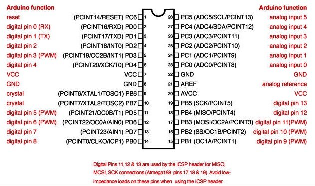
ATM328_arduino_pinout
DSC_0344_small

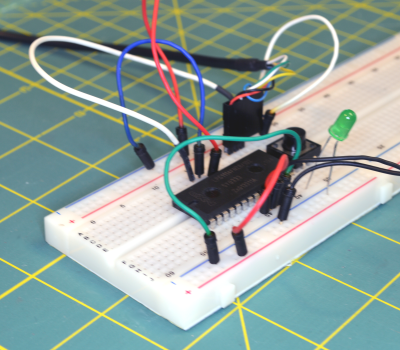
What are we doing here ? Verifying that our bare circuit works just we intend it to before moving on to designing the PCB.

PCB design and production

Now that we have set our minds on a specific circuit design, it’s time to make a beautiful schematic using Eagle ! Once the schematic is done, you can start to make the PCB layout itself. Sparkfun wrote a guide explaining how to complete these two steps with Eagle:

You can find some tips about eagle here and over there is a tool allowing you to compute the optimal trace width according to your circuit specifications.

The question you ought to ask yourself at this point is : what are the requirements that will shape your circuit ? Do you want through holes or surface mounted components ? SMD components mean lowering the cost of assembly for high production volumes (a pick and place machine once configured will be able to make pretty much any quantity for ridiculous marginal price increase, whereas through holes components need to be places by hand in most places). On the other hand, if you don’t have a reflow oven and just want to make a few boards for yourself, you will probably prefer the through hole option. It is a also a good pick if you intend to sell or distribute your product as a kit of parts to solder.

Always keep in mind the overall design of your product too, it might influence the form-factor of your board or vice-versa.

So let’s assume that we’ve answered these questions. We now have our circuit schematic and board layout! Get the files here.

MoodCubeSchematic-revision
MoodCubeLayout-revision

The next step is to actually make the board. Will you do it yourself or have it produced ? It’s your call and it certainly depends on the requirements of your projects. You can find info about the DIY way here.

If you want to have it produced, the question will be : should I go for a local or a Chinese company ? Once again it depends on how rushed you are (local companies usually have a quick turnaround option but it comes at a price. As an example I paid 140$ca toAPCircuits for 4 boards with top and bottom soldermask + top silkscreen. It arrived 5 days later and the quality of the boards was very high standard). If I had ordered them from china, I probably could have had 10 boards for 14$ delivered in 2/3 weeks. I feel like I have to mention what every professional told me when speaking about outsourcing the production to China : apparently they WILL make a copy of your plans just in case it could be sold in their own market. I have no idea how true this is, but about five different persons told me to think twice about that “fact”. (I would love to have some insight about that in the comments).

So, that being said, here is a few links :

  • Ladyada PCB manufacturers list.
  • PCB Shopper : price comparison website.
  • OSH Park : “OSH Park is a community printed circuit board (PCB) order.” Worth to mention that they accept Eagle files on top of the usual gerbers.
  • Seedstudio : a SF based company acting as an intermediary between you and Shenzen. They offer PCB prototyping, soldering and 3d printing services for a very attractive rate.
  • Dirty PCBs : “No bull, just crappy PCBs” from China.

Apart from the PCB, you will need a solder stencil if your components are surface mounted. The stencil is used to apply the solder paste on your circuit. The components are then placed (manually or with a pick and place machine) on your board and it goes in the oven where the past melts on the pads of your components. As always, you will have to make a tradoff between the quality of your stencil and the price you are willing to pay. You can get a thin laser-cut plastic one from OSH stencil for 10$ a piece or astainless steel version for 125$.

Seems like the PCB part of our project is taken care of so what now ? Let’s start to design the enclosure!

Enclosure design and 3d printing

We will use Sketchup to help us with the CAD job and Meshlab to verify the integrity of the .stl files generated.

First export a model of your PCB from Eagle so that we can design around it using a very convenient extension : Eagle Up. Browse Sketchup’s 3d warehouse in order to find components to fill the board (if you want to of course). Very often the scale is in meters and you’ll have to scale everything down (this is because Sketchup was made for architecture modelling purposes so it’s not optimized for sub-meter precision. Thus it’s common to design in meters and at the end scale down to the real size).

circuit_blank
circuit_with_parts

Then you can start to design your enclosure. Here are some resources that helped me :

But let’s get back to our MoodCube ! What do we need ? Basically just a base to accommodate the circuit and the battery, and a cube coming on top of it acting as a light diffuser. White acrylic is a good pick for such an application, but standard PLA/PBS should do the trick as well.

The bottom holds to the top thanks to a single screw and little plastic piece that will fit into a slot made on the top part.

As for the battery holder, I didn’t bother too much and went for this model since I could find the 3d model of their product easily.

MoodCube2
MoodCube6

Here is the result. Once you are satisfied with your design you can use the Solid Inspector tool to check if your components are solids. If they pass the test, you can then export the model in .stl thanks to yet another extension and perform a last water-tightness test in Meshlab (or whatever CAD software you prefer).

MoodCube3
MoodCube4
MoodCube1
MoodCube0

All the corresponding files can be found here.

A piece of advice : make extensive use of the “Make component” functionality. This way if parts of your model are copies of one another, you’ll just have to modify one and the change will be applied on all copies of the component. Plus like in programming, modularity and re-usability is the key so it’ll really make your life easier.

Now we want to print our model right ? If you’re like me and don’t have access to a 3d printer, you will have to rely on someone else to do that for you. Having something 3d printed can get expensive pretty quickly depending on the volume of your model. I was a bit baffled by the price at first, and if you are too I’ll tell you the same thing I was told : you’re not only paying for the plastic used to print your part, but also for the time of the machine, the time of the machinist and the high depreciation of the value of the machine itself. + most of the time a little rework is performed on your model by the guy that prints it, so you have to pay for his expertise too.

That being said, keep in mind that printers don’t print at 100% density. Which means that if your model has a volume of 100 cubic centimeters and the printer’s rate is 1$/cc, you wont end up paying 100$. The filling density is usually between 15 and 40% (the more density, the more resistant you material will be) so you will be paying approximately between 15 and 40$ (their usually is a fixed starting price added to the variable one).

Shapeway is a big player in this area but I find that they are quite expensive. Personally I prefer to go on 3dHubs and look for a local actor. I like to that because you are in a strong position to negotiate : there seems to be a lot more people trying to make a little profit with their 3d printer than there is demand so they are being super nice to you in order to get good reviews and start a clientele.

Here ends my experience regarding this topic. I hope that you found what you were looking for, or at least some of it. If you would like to add something, please say so in the comments and I’ll gladly see to it.

Additional resources

Edit 1 : on the good advice of [Milumet] from Reddit and other commentaries about my poor choice of voltage regulator I replaced the MCC7805CT by a L7800 and also added two capacitors on Vin and Vout as stated in the datasheet. Which leads me to a piece of advice I forgot to follow myself : always go look at the application circuits section of the datasheet of the components your are using.

+ tied the RESET pin to Vcc so that it’s not left floating. Why ? because a pin left in a floating state can jump from one state to the other because of the weakest surrounding electrical noise and we don’t want the MCU to reboot incessantly do we ? I had the case of a simple counter incremented by a push-button : the button was not inserted right in the breadboard so the pin was effectively floating and the counter would increment like crazy when I hovered my hand on top of the circuit. I was starting to believe that magic was real and expected a fairy to appear when I remembered : the pin was in a floating state, and the noise generated by my body was enough to get the pin’s state oscillating.

+ generated the corresponding gerber files.

Edit 2 : added OSH park to the list of PCB manufacturer since they were mentioned very frequently.

Edit 3 : added an electronics section to the Resources page.


Particle Universal Gateway for ULPNode and others RF nodes

$
0
0

Currently working with Ultra Low Power nodes project (formerly ULPNode), I was searching for a small but powerfull gateway.

What job for this gateway ?

My goal is to be able to do a lot of thing with the gateway, even having an IHM with touch screen for example. I also want the Gateway act as a Node Management. The gateway must have a Web Interface to be able to do some basic action such as Node configuration (ID, NetId, Sensors configuration of attached node, …)

The gateway will be responsible of node ID attribution, acting like a DHCP server, once a new node is discovered and/or put in configuration mode, it can be connected to the network just like a classic computer, the Gateway will dedicate to it a specific Node ID, and once this node ID will be affected, the possibility to configure the node through the gateway web interface.

Another function of the Gateway will be to push the data to a IoT server  (local or cloud) such asEmoncms or whatever dashboard available like Blynk (for phone and tablet), AdafruitParticle Dashboard or freeboard. Today I did not found any descent (for free) IoT management data, hoping this will change in the next couple of months with IoT growing (but if you know good one, just let me know).

Oh, last but not least, I do not want to use a Raspberry Pi for this, really a personal choice, but for something reliable running 7/24 I absolutely do not trust any SD card when starting a database on it. In all case, one day, time will give me reason, SD will die starting by strange lockout and behavior. Except setting the system into read only mode, no way for me!

Moreover I want the gateway to be smart enough to be moved my hand from one point to another for quick testing, connected with a Lipo for example. That said, I started to design a Gateway with classic connection for testing.

What’s on ?

The gateway will host several funny things like

  • Socket to plug a Spark Core or Particle Photon
  • Pins to connect I2C or SPI OLED 128×64
  • Pins to connect 2.2″ or 1.8″ TFT LCD
  • RFM69 or RFM12B on board module
  • Lipo Battery connector for testing and move the Gateway (no charger on board)
  • 3V3 On board regulator for harvesting devices if any to avoid pumping from Particle Regulator
  • Data connection for any cheap ebay ASK RX receiver
  • FTDI connection for those who want to debug serial or send data over real serial
  • 2 x grove I2C connector to connect other I2C devices

I started this design long time ago, with Spark Core available. If it was today, may be I use some kind of ESP8266 or OAK, but I love Particle Photon and their future dashboards, so, I keep it like this. But I think this is totally tweakable to change socket for hosting a ESP8266 or OAK board

Design ?

Schematic are very simple, it’s just more “wiring stuff” than any smart components placement. This boards keeps things minimal but powerfull. It can be easily hand soldered in less than 10 minutes. I’ve  put

  • An optional cheap regulator if you think you will need more current than the on board Particle regulator can drive.
  • 2 x 10uF capacitors around the regulator
  • 2 x 4K7 pullups resistors on I2C bus
  • RMF69 / RFM12B optional RF receiver of course (need it)
  • That’s all !!!!

Schematics

Here are the schematic of this board

Particle Gateway Schematic

Particle Gateway Schematic

Board Pictures

Particle Gateway Assembled

Particle Gateway with RFM69HW

Particle Gateway with Spark Core

Particle Gateway with OLED

Working code

I worked on a French project that use OLED Display and RFM69 module using Lowpowerlab RFM69library so I ported the RFM69 library to work on Spark core, you’ll find it in the full working project. But you’ll need to grab the code you need, it’s really a project with lot of libraries into and must be compiled with spark-dev (not with Particle Web IDE). You can find this french project here

The future ULPNode gateway will work with another RF lib called RadioHead, but for now I did not realized the port since we can’t have a classic “library” folder (see https://github.com/spark/spark-dev/issues/71)
Same thing for U8Glib display library which I like to port, but still no success to do it (seehttps://community.particle.io/t/using-u8glib-for-spark-super-beginner-question-alert/5794/59)

Reference

That said, I hope you’ll find this shield useful and you’ll do a lot of funny things with this simple board, let me know if you use it and what you do 😉

Charles


LPC810 Cortex-M0+ Programming from Scratch

$
0
0

LPC810 Cortex-M0+ Programming from Scratch – Part 1: LED Blink

http://homepages.rpi.edu/~dongr2/

Disclaimer: I am no ARM programming expert, and I myself am experimenting with all the things described in this series of, “tutorials”. Therefore, I might be totally wrong in reasoning, but the code should be usable.

What this (series) is about?

I am currently experimenting with the LPC810 chip on Linux using the GCC toolchain. This is more like a progress of my experiment, but I hope it will help others. Actually it is more about compiler and linker than about embedded programming, because honestly, I don’t have any problem on general purpose embedded programming since I have prior experience using AVR and STM32 with preexisting librariessuch as AVR-LibC or STM32 Standard Peripheral Library. However, this time I am going to start from scratch. Which means, starting from assembly, linker scripts, startup code, etc. Since I can’t find any “standard” NXP LPC810 C headers, I will write my own.

The LPC810

More specifically, the LPC810M021FN8, is a small ARM Cortex-M0+ chip with 4kB flash and 1kB SRAM. Not much, right? However, the best part is that it comes as a DIP-8 package, which means you can plug it right to a breadboard and start experimenting. Also, it is amazingly cheap comparing to other ARM chips: as of the date of writing, 2014-11-27, the price on Mouser is $2.41.

This chip does have a lot of limitations though. The one biggest down side for me is that it doesn’t come with Analog-Digital Converter. It does have two Analog-Digital Comparaters, though. The next obvious reason is that there are only 6 GPIOs, where one is taken by RESET(PIO0_5), and two are not enabled by default(PIO0_2 and PIO0_3, taken by SWD interface). However, this chip should be enough to experiment with ARM Startup and linker scripts and other good stuff.

Disclaimer again: I am only starting to experiment with compilers/linker scripts, so I write terrible linker scripts. I miss multiple sections because I don’t know what they do. As of the time I write this post, I only have the .text, .data, .bss section written because I don’t understand what everything else are.

Reader assumptions

  • Can use GNU/Linux (I am using GNU/Linux to do everything. Probably works on Windows, but need extra knowledge).
  • Knows basic assembly (Sorry, I am not good enough to teach this).
  • Knows basic C (I can talk about this, though)
  • At least programmed some embedded device before(like 8051 or AVR)
  • Knows how to read datasheet
  • Knows how to wire up a breadboard without a photo or schematic (I admit I am just lazy. The circuit is too simple anyway).

What you will need

  • An LPC810 chip. Here I am using LPC810M021FN8.
  • A TTL-USB cable, 3.3V.
  • A piece of breadboard.
  • An indicator LED rated around 10mA (Or, just a random small 3mm/5mm LED).
  • A resistor around 330Ω.
  • Two pushbuttons.
  • LPC81xM Datasheet
  • LPC81x User Manual
  • Cortex-M0+ Devices Generic User Guide
  • ARM Toolchain. If you don’t have experience, get a precompiled one. I have several experience that when I compile my own and encountered some unsolvable problems, simply changing the toolchain fixed the problem. Try the gcc-arm on Ubuntu/Debian or the CodeSourcery toolchain.
  • lpc21isp. The downloader.

Hardware Wiring

Wire the 3.3V to Pin 6(Vdd) of the LPC810. Connect ground to Pin 7(Vss).

Connect Pin 5 to ground through a pushbutton. When Pin 5 is pulled down(i.e. the pushbutton is being pressed) during reset, chip enters ISP command handler, and can be programmed.

Connect Pin 4(PIO0_2) to LED, series with resistor to ground. Pin 2 is the TXD in ISP mode, Pin 8 is the RXD in ISP mode. Connect them accordingly to the RX/TX pin of the TTL-USB converter. Note: my converter has its TX/RX label reversed for some version, so I have to connect TXD to TXD and RXD to RXD.

Connect Pin 1 to ground through a pushbutton. If you do not connect this button, you can still reset the device by removing the power and then power on.

Software Preparation

Install toolchain and lpc21isp (Ubuntu/Debian)

apt-get install gcc-arm-none-eabi lpc21isp

Done!

Start Coding!

Just test hardware

Example Source Code if you like to just download and try: 01-Getting_Started.tar.xz

Unpack the file somewhere you can remember. Plug the TTL-USB cable in(with the breadboard, of course). Hold the reset button, then hold the ISP button. Please try to push the buttons in this sequence, otherwise if you have set the pin that connects to the ISP button to output and HIGH, think what would happend when you push that down before the controller is reset. Still holding ISP button, execute

make flash

in the directory using UNIX command line(I assume you know how to do so). You should see something like this:

lpc21isp main.hex /dev/ttyUSB0 115200 12000
lpc21isp version 1.94
File main.hex:
    loaded...
    converted to binary format...
    image size : 276
Image size : 276
Synchronizing (ESC to abort). OK
Read bootcode version: 4
13
Read part ID: LPC810M021FN8, 4 kiB FLASH / 1 kiB SRAM (0x00008100)
Will start programming at Sector 1 if possible, and conclude with Sector 0 to ensure that checksum is written last.
Erasing sector 0 first, to invalidate checksum. OK
Sector 0: ..|.
Download Finished... taking 0 seconds
Now launching the brand new code

Then, press the reset button again. LED should blink.

Starting from Scratch

In this section, I will explain the process of starting from scratch, and explain every details of the source code.

Directory and Makefile

Make a new folder, say, 00-Getting_Started. Create a Makefile:

TGT = main
CSRC =
ASRC =
ASRC += crt0.S
CSRC += main.c
LDS = ./LPC810/lpc810.ld

OBJS = $(CSRC:.c=.o)
OBJS += $(ASRC:.S=.o)

CC=arm-none-eabi-gcc
OBJCOPY=arm-none-eabi-objcopy
OBJDUMP=arm-none-eabi-objdump
NM=arm-none-eabi-nm
SIZE=arm-none-eabi-size

FLASH = lpc21isp
PORT = /dev/ttyUSB0
BAUD = 115200
KFREQ = 12000

CFLAGS=-O0 -mthumb -mcpu=cortex-m0plus -nostartfiles -Wl,-T$(LDS),-nostdlib,-Map=$(TGT).map

all: $(TGT).hex

%.o: %.S
	$(CC) $(CFLAGS) -c $^ -o $@

$(TGT).elf: $(OBJS)
	$(CC) $(CFLAGS) $(LDFLAGS) $^ -o $@

$(TGT).hex: $(TGT).elf
	$(OBJCOPY) $< -O ihex $@
	$(OBJDUMP) -D $< > $(TGT).disasm
	$(NM) -n $(TGT).elf > $(TGT).sym
	$(SIZE) $(TGT).elf

clean:
	rm -rf *.elf *.hex *.map *.o *.disasm

flash:
	$(FLASH) $(TGT).hex $(PORT) $(BAUD) $(KFREQ)

Of course, this is not the best Makefile in the world, but good enough for this series.

Then, create the folders and files referenced by the Makefile:

mkdir -pv LPC810
touch main.c crt0.S LPC810/lpc810.ld

Main code

Here comes the main code(main.c):

 1 /**
 2    Author: Rongcui Dong
 3
 4    This is the main code for the LPC810/Cortex-M0+ tutorial series:
 5    00-Getting_Started.
 6    Originally posted on:
 7    http://homepages.rpi.edu/~dongr2/
 8
 9    Inspired by http://midibel.com/blink0.html, but I rewrote the whole
10    thing
11
12    Licence: Do anything with it, I don't care. Public Domain. Just
13    remember I don't give any warrenty
14 */
15
16 typedef unsigned int volatile * vp;
17 void main() {
18   /* PIO0_2 is used by SWD, so disable it */
19   *(vp) 0x4000C1C0 = 0xFFFFFFBFUL;	/* PINENABLE0 register */
20   /* Set GPIO Direction */
21   *(vp) 0xA0002000 |= 1 << 2;	/* DIR0, set PIO0_2 to output */
22   for(;;) {
23     /* Toggle the LED */
24     *(vp) 0xA0002300 |= 1 << 2;	/* NOT0 register */
25     volatile long wait = 240000;
26     while (wait > 0) --wait;		/* WAIT */
27   }
28 }

There is nothing fancy. The special memory addresses are the device specific addresses to control hardware. In order to access those, the addresses are cast into volaile pointers. These addresses can be found under the LPC81x User Manual. The PINENABLE0 address is found in Chapter 9, LPC81x Switch Matrix, the DIR0 and NOT0 addresses are under Chapter 7, LPC81x GPIO Port. I will only point the location in this tutorial, and I will not do so for the next ones. First, the SWD related functions are disabled so that the LED pin has GPIO enabled:

*(vp) 0x4000C1C0 = 0xFFFFFFBFUL;    /* PINENABLE0 register */

Then, PIO0_2 is set to output mode:

*(vp) 0xA0002000 |= 1 << 2;

In an infinite loop, the LED is toggled by writing to the NOT0 register:

*(vp) 0xA0002300 |= 1 << 2;    /* NOT0 register */

To slow down the blink enough, we just waste a lot of cycles doing nothing.

volatile long wait = 240000;
while (wait > 0) --wait;        /* WAIT */

That’s it for the main.c. Simple. However, with only this source file, the linker can’t know where to put the code in the executable. Therefore, we need to tell it where to put what. In the next section, I will talk about how we instruct the linker to correctly place code.

Linker Script

Now let’s look at the LPC810/lpc810.ld.

 1 /**
 2     Author: Rongcui Dong
 3
 4     This is the linker script for the LPC810/Cortex-M0+ tutorial series:
 5     00-Getting_Started.
 6     Originally posted on:
 7     http://homepages.rpi.edu/~dongr2/
 8
 9     Licence: Do anything with it, I don't care. Public Domain. Just
10     remember I don't give any warrenty
11  */
12
13 ENTRY(Reset_Handler);
14 MEMORY {
15     FLASH(rx) : ORIGIN = 0x0, LENGTH = 4K
16     RAM(rwx) : ORIGIN = 0x10000000, LENGTH = 1K
17 }
18
19 SECTIONS {
20     . = ORIGIN(FLASH);
21     .text : {
22         KEEP(* (.isr_vectors));
23 	. = ALIGN(4);
24 	. = 0xC4;		/* The end of vectors. Just for tutorial 0 */
25 	__vec_end__ = .;
26 	* (.text);
27 	. = ALIGN(4);
28 	__end_text__ = .;
29     } > FLASH
30     __stack_top = ORIGIN(RAM) + LENGTH(RAM);
31 }
32
33 __end = .;
34 PROVIDE(etext = __end_text__);
35 PROVIDE(end = .);

An executable is divided into multiple sections. Each section is placed into a storage device in the microcontroller. The starting address and size are documented in 81x Datasheet, in section Memory Map. In our case, an LPC810 has 4K flash and 1K RAM, starting at address 0x00000000 and0x10000000, therefore, we have the following snippet of LD script(ignore the ENTRY() for now):

MEMORY {
    FLASH(rx) : ORIGIN = 0x0, LENGTH = 4K
    RAM(rwx) : ORIGIN = 0x10000000, LENGTH = 1K
}

This means there are two storage devices, FLASH and RAM. FLASH is readable and executable, while the RAM is readable, executable, and writable. FLASH starts at 0x0 and is 4KB long, whileRAM starts at 0x10000000 and is 1KB long. FLASH device is the read only permanent memory where the code stays, and RAM is the working memory when the code runs.

After storage devices are defined, we need to tell the linker specific information about where each sections go. Before explaining the script, we need to know some information about the Cortex-M0+ processor. In the Cortex-M0+ Devices Generic User Guide, section 2.3.4 Vector Table, we see that a vector table comes at the very first of the memory address: 0x00000000. It stores the initial stack pointer value, and then 15 addresses of the core Cortex-M0+ exception handlers. After that, there are device specific interrupt handler addresses. Note that since this is a 32 bit device, each address takes 4 bytes. According to the LPC81x User Manual(Will be abbreviated as 81X Manual), section 3.3.1 Interrupt Sources, there are 32 interrupt sources. Therefore, the first 48 long(4 bytes wide each) values are taken by the vector table, so the executable codes will go after them. In other words, the executable code starts at address (48+1)*4 = 0xC4

.

Now we can look into the code.

. = ORIGIN(FLASH);

This means the “current” address is set to the origin of FLASH. This line tells the linker to place code starting at this address.

.text : {
    KEEP(* (.isr_vectors));
. = ALIGN(4);
. = 0xC4;        /* The end of vectors. Just for tutorial 0 */
__vec_end__ = .;
* (.text);
. = ALIGN(4);
__end_text__ = .;
} > FLASH

.text is the target section that the code will be placed into. In order to make sure the vector table isalways placed before anything, we make it a seperate section, in this case, .isr_vectors. TheKEEP here is just telling the linker that it should never discard this section even if it is not referenced (affected by -Wl,--gc-sections). When source files are compiled, different object files are generated, main.o and crt0.o in this case. Now we go over the syntax even more carefully.

.text : {
...
} > FLASH

This means the target section is .text, and it will be put on the storage device FLASH.

* (.isr_vectors);

This means for all object files (indicated by wildcard *), copy the .isr_vectors section into the target address. In this case, 0x0.

. = ALIGN(4);

Since Cortex-M0+ is 32 bits, each instruction is 4 bytes wide. Therefore, we need to align the code to instructions before advancing to next section. If it is not aligned, the linker just appends 0x0 (that is an observation, not necessarily true).

. = 0xC4;

This line is just for this tutorial because otherwise you have to type a whole list of 48 vectors and create 48 function definitions before you can even start blinking an LED. We all know from above that the actual executable starts at 0xC4, so this is totally fine(and I have tested it, so really, it is fine). Of course, you can still keep this line for the next tutorials if you like.

__vec_end__ = .;

This is just a symbol for use in source codes. __vec_end__ will store the current address, and can be referenced by C or assembly code.

* (.text)

This is the same meaning as before. Copy the .text section from each object file, put it in the executable.

__stack_top = ORIGIN(RAM) + LENGTH(RAM);

This defines the begining of the stack, which locates at the end of RAM and grows towards the front.

Finally, we have some more symbols defined about the end of code. Now we come back to the first line:

ENTRY(Reset_Handler)

This means the ‘entry point’ of the executable is the symbol Reset_Handler, i.e. when the device starts, the first executed instruction is at the address of symbol Reset_Handler. Note thatReset_Handler does not need to be a function, it can be any symbols(I think it needs to be global, though). Although I haven’t tested it, a plain address should also work in this definition.

Startup Code

Now we have the correct placement of the sections. However, we still need to write the vector table and the code to execute main(). After all, our entry point is Reset_Handler, not main. Let’s look atcrt0.S:

 1 /**
 2     Author: Rongcui Dong
 3
 4     This is the startup code for the LPC810/Cortex-M0+ tutorial series:
 5     00-Getting_Started.
 6     Originally posted on:
 7     http://homepages.rpi.edu/~dongr2/
 8
 9     Licence: Do anything with it, I don't care. Public Domain. Just
10     remember I don't give any warrenty
11 */
12 	.syntax unified
13 	.thumb
14
15 	.section .isr_vectors
16 	.align
17 	.long __stack_top
18 	.long Reset_Handler
19
20 	.text
21 	.align
22
23 	.thumb_func
24 	.global Reset_Handler
25 Reset_Handler:
26 crt0:
27 	b main

First, we have something to tell the assembler:

.syntax unified
.thumb

This tells the assembler(GNU AS in this case) to use Unified Assembler Language and Thumb instructions.

Now we start with the vector table.

.section .isr_vectors

This tells the assembler to place the later code into section .isr_vectors.

.align

As it looks like, this tells the assembler to align code to 4 byte instructions.

.long __stack_top
.long Reset_Handler

This defines two long expressions. The first one contains the symbol __stack_top, defined in linker script. The second one contains the symbol Reset_Handler, which is defined later. Notice that the first .long takes the addresses 0x00 to 0x03, and the second .long takes 0x04 to 0x07. Recall the vector table in Cortex-M0+ Devices Generic User Guide (will be abbreviated as CM0 Guidefrom now on), the first long is indeed the initial stack pointer, while the second one is the address of the program counter after a reset. Since we already set the beginning of .text to be 0xC4, we don’t need to define all the other vectors. Convenient, right?

.text

This means put the later code into the .text section. This line is the same as .section .text.

.thumb_func

This line is needed for GNU AS to generate correct mix of Thumb/ARM instructions. I don’t know a lot about this, but I know that if this line is omitted, the generated executable is incorrect.

.global Reset_Handler

This line makes symbol Reset_Handler to be global, so that code from other source files can access this symbol.

Reset_Handler:
crt0:
    b main

Why do I have two symbols but nothing between? Because there will be some initialize code there for the next tutorials. These three lines are the minimal code to execute the main(). For newbies(like me), notice that the symbols don’t take up memory, so the only line of code here is b main. As documented in both CM0 Guide and 81x Manual, B{cc} <label> is the instruction for “Branch to <label> {conditionally}”. In this case, “branch to label main unconditionally”.

Now the startup code is finished. Do the same thing as compiling the example:

make
make flash

Don’t forget to press the ISP button. Also don’t forget to reset after programming. After reset, you should see the LED blink!

Some Notes

If you look at the disassembled file main.disasm, in the first ‘subsection’ under section .text, you will see:

Disassembly of section .text:

00000000 <main-0xc4>:
   0:   10000400        andne   r0, r0, r0, lsl #8
   4:   00000111        andeq   r0, r0, r1, lsl r1

According to dwelch’s reply in this post, the address of all exception handlers should be odd. Remember the first item is the initial stack pointer, so that is correct.

LPC810 Cortex-M0+ Programming from Scratch – Part 2: .data and .bss

Part 1

In this tutorial, we are going to finish the vector table and the initialization of .data and .bss section. The tutorial will continue based on Tutorial 1. If you want the entire working code, 02-BSS_Data.tar.xz.

Basics about .rodata, .data and .bss

Disclaimer again: I am not expert on this topic, so I can be wrong.

.rodata contains the constant variables in C. Such as:

const unsigned int variable = 1;

.data section contains initialized variables in C. Such as:

unsigned int variable = 1;

.bss section contains uninitialized variables. Such as:

unsigned int variable;

Typically, the data in .bss section is initialized as zero.

Linker Script

I will attach the entire linker script at the end of this section. Now I will just go over the details.

.rodata Section

First, since .rodata is just constants, it doesn’t need to be copied to RAM. After all, our small device only contains 1KB of RAM. Therefore, we change the .text section definition like this:

.text : {
    KEEP(* (.isr_vectors));
    . = ALIGN(4);
    __vec_end__ = .;
    /*. = 0xC4;*/ /* End of vectors */
    * (.text);
    * (.text*);
    . = ALIGN(4);
    * (.rodata);
    * (.rodata*);
    . = ALIGN(4);
    __end_text__ = .;
} > FLASH

The above code will tell the linker to put .rodata directly after .text of each object file, and into the.text section of the generated executable. Note the (.text*) is here because sometimes there are some .text.something generated by the compiler.

.data Section

This section is somewhat different from the previous ones. Apparently, at execution, all data is in RAM, but since they contain initialized values, they have to be stored into flash. Therefore, the .data section has two addresses: load address and run-time address. The labels in .data section should be in run-time address in order for the program to access and change the value. Now we will look into the details of the definition of this section.

.text : {
    ...
} > FLASH

__flash_sdata__ = .;

.data : AT(__flash_sdata__) {
    ...
} > RAM

Here, the __flash_sdata__ symbol is the address right after the .text section, and is where.data section is stored. In other words, __flash_sdata__ is the beginning of the load address of the .data section. Since the labels are using run-time address, there is the > RAM.

.data : AT(__flash_sdata__){
    __data_start__ = .;
    * (.data);
    * (.data*);
    . = ALIGN(4);
    __data_end__ = .;
} > RAM
__data_size__ = __data_end__ - __data_start__;

The __data_start__ and __data_end__ are the start and end of run-time address. The others are have familiar syntax, so I will not explain here. The labels will be used by startup code later.

.bss Section

The .bss section has no initial value, so it only has a run-time address.

.bss : {
    __bss_start__ = .;
    * (.bss);
    * (.bss*);
    . = ALIGN(4);
    __bss_end__ = .;
} > RAM
__bss_size__ = __bss_end__ - __bss_start__;

The syntax is the same, so I won’t explain.

The entire Linker Script

Note: Since the above code snippet are copied and pasted into the post, while the following one is included directly, I may forget to update the above snippets. Please use this one as the correct reference.

/**
    Author: Rongcui Dong

    This is the linker script for the LPC810/Cortex-M0+ tutorial series:
    02-BSS_Data
    Originally posted on:
    http://homepages.rpi.edu/~dongr2/

    Licence: Do anything with it, I don't care. Public Domain. Just
    remember I don't give any warrenty
 */
ENTRY(Reset_Handler);
MEMORY {
    FLASH(rx) : ORIGIN = 0x0, LENGTH = 0x1000 /* 4K */
    RAM(rwx) : ORIGIN = 0x10000000, LENGTH = 0x400 /* 1K */
}

SECTIONS {
    . = ORIGIN(FLASH);
    .text : {
        KEEP(* (.isr_vectors));
        . = ALIGN(4);
        __vec_end__ = .;
        /*. = 0xC4;*/ /* End of vectors */
        * (.text);
        * (.text*);
        . = ALIGN(4);
	* (.rodata);
	* (.rodata*);
	. = ALIGN(4);
        __end_text__ = .;
    } > FLASH

    __flash_sdata__ = .;

    .data : AT(__flash_sdata__){
    	__data_start__ = .;
        * (.data);
        * (.data*);
        . = ALIGN(4);
	__data_end__ = .;
    } > RAM
    __data_size__ = __data_end__ - __data_start__;

    .bss : {
        __bss_start__ = .;
    	* (.bss);
    	* (.bss*);
        . = ALIGN(4);
        __bss_end__ = .;
    } > RAM
    __bss_size__ = __bss_end__ - __bss_start__;
    __stack_top = ORIGIN(RAM) + LENGTH(RAM);
}

_end = .;
PROVIDE(end = .);

Vector Table and Startup Code

The startup file

This section only gives the startup file crt0.S. Details will be explained later

/**
    Author: Rongcui Dong

    This is the startup code for the LPC810/Cortex-M0+ tutorial series:
    02-BSS_Data
    Originally posted on:
    http://homepages.rpi.edu/~dongr2/

    Licence: Do anything with it, I don't care. Public Domain. Just
    remember I don't give any warrenty
*/

	.syntax unified
	.thumb
	.section .isr_vectors

	.align 2

	.long __stack_top
	.long Reset_Handler
	.long NMI_Handler
	.long HardFault_Handler
	.long 0
	.long 0
	.long 0
	.long 0
	.long 0
	.long 0
	.long 0
	.long SVCall_Handler
	.long 0
	.long 0
	.long PendSV_Handler
	.long SysTick_Handler
	.long 0

	/* IRQ 0 */
	.long SPI0_IRQ
	.long SPI1_IRQ
	.long 0
	.long UART0_IRQ
	.long UART1_IRQ
	.long UART2_IRQ
	.long 0
	.long 0
	/* IRQ 8 */
	.long I2C0_IRQ
	.long SCT_IRQ
	.long MRT_IRQ
	.long CMP_IRQ
	.long WDT_IRQ
	.long BOD_IRQ
	.long 0
	.long WKT_IRQ
	/* IRQ 16 */
	.long 0
	.long 0
	.long 0
	.long 0
	.long 0
	.long 0
	.long 0
	.long 0
	/* IRQ 24 */
	.long PININT0_IRQ
	.long PININT1_IRQ
	.long PININT2_IRQ
	.long PININT3_IRQ
	.long PININT4_IRQ
	.long PININT5_IRQ
	.long PININT6_IRQ
	.long PININT7_IRQ

	.text
	.align

	.thumb_func
	.global Reset_Handler
Reset_Handler:
	cpsid i
	ldr r0, =__flash_sdata__
	ldr r1, =__data_start__
	ldr r2, =__data_size__

	@@ If data_size == 0
	cmp r2, #0
	beq init_bss

copy:
	ldrb r4, [r0]		@ Load *r0 to r4
	strb r4, [r1]		@ Load r4 to *r1
	adds r0, #1		@ Increment flash pointer
	adds r1, #1		@ Increment RAM pointer
	subs r2, #1		@ Loop until all data are copied
	bne copy

init_bss:
	ldr r0, =__bss_start__
	ldr r1, =__bss_end__
	ldr r2, =__bss_size__

	cmp r2, #0
	beq crt0

	movs r4, #0
zero:
	strb r4, [r0]		@ Zero out
	adds r0, #1		@ Increment pointer
	subs r2, #1
	bne zero

crt0:
	cpsie i
	b main
.align

Vector Table

This part is just work: Copy everything from the CM0+ Guide(Cortex-M0+ Devices Generic User Guide) and 81x Manual(LPC81x User Manual). It is just that long list of .long expressions (really, longexpressions). Note that currently none of the added labels are defined yet, so we are going to define them. Since we all like C instead of assembly(at least, for me), we are going to define them in a C file. Here comes vector.c:

extern void Reset_Handler(void);
extern void NMI_Handler(void);
extern void HardFault_Handler(void);
extern void SVCall_Handler(void);
extern void PendSV_Handler(void);
extern void SysTick_Handler(void);

extern void SPI0_IRQ(void);
extern void SPI1_IRQ(void);
extern void UART0_IRQ(void);
extern void UART1_IRQ(void);
extern void UART2_IRQ(void);
extern void I2C0_IRQ(void);
extern void SCT_IRQ(void);
extern void MRT_IRQ(void);
extern void CMP_IRQ(void);
extern void WDT_IRQ(void);
extern void BOD_IRQ(void);
extern void WKT_IRQ(void);
extern void PININT0_IRQ(void);
extern void PININT1_IRQ(void);
extern void PININT2_IRQ(void);
extern void PININT3_IRQ(void);
extern void PININT4_IRQ(void);
extern void PININT5_IRQ(void);
extern void PININT6_IRQ(void);
extern void PININT7_IRQ(void);

__attribute__((naked))
void _unhandled_exception(void) {
    for(;;);
}

void NMI_Handler(void) __attribute__((weak, alias("_unhandled_exception")));
void HardFault_Handler(void) __attribute__((weak, alias("_unhandled_exception")));
void SVCall_Handler(void) __attribute__((weak, alias("_unhandled_exception")));
void PendSV_Handler(void) __attribute__((weak, alias("_unhandled_exception")));
void SysTick_Handler(void) __attribute__((weak, alias("_unhandled_exception")));

void SPI0_IRQ(void) __attribute__((weak, alias("_unhandled_exception")));
void SPI1_IRQ(void) __attribute__((weak, alias("_unhandled_exception")));
void UART0_IRQ(void) __attribute__((weak, alias("_unhandled_exception")));
void UART1_IRQ(void) __attribute__((weak, alias("_unhandled_exception")));
void UART2_IRQ(void) __attribute__((weak, alias("_unhandled_exception")));
void I2C0_IRQ(void) __attribute__((weak, alias("_unhandled_exception")));
void SCT_IRQ(void) __attribute__((weak, alias("_unhandled_exception")));
void MRT_IRQ(void) __attribute__((weak, alias("_unhandled_exception")));
void CMP_IRQ(void) __attribute__((weak, alias("_unhandled_exception")));
void WDT_IRQ(void) __attribute__((weak, alias("_unhandled_exception")));
void BOD_IRQ(void) __attribute__((weak, alias("_unhandled_exception")));
void WKT_IRQ(void) __attribute__((weak, alias("_unhandled_exception")));
void PININT0_IRQ(void) __attribute__((weak, alias("_unhandled_exception")));
void PININT1_IRQ(void) __attribute__((weak, alias("_unhandled_exception")));
void PININT2_IRQ(void) __attribute__((weak, alias("_unhandled_exception")));
void PININT3_IRQ(void) __attribute__((weak, alias("_unhandled_exception")));
void PININT4_IRQ(void) __attribute__((weak, alias("_unhandled_exception")));
void PININT5_IRQ(void) __attribute__((weak, alias("_unhandled_exception")));
void PININT6_IRQ(void) __attribute__((weak, alias("_unhandled_exception")));
void PININT7_IRQ(void) __attribute__((weak, alias("_unhandled_exception")));

Before compiling, don’t forget to add this file to CSRC in the Makefile.

The function prototypes all have the extern keyword, since the handler can be declared outside thevector.c. However, to make development easier, we don’t want to declare all those handlers before starting to blink an LED, so we first make a naked function _unhandled_exception() which just does an infinite loop, so that when the processor receives an unhandled exception, it will ‘stop’, although it is running.

__attribute__((naked))

This basically means the C compiler is not saving context of this function, so current registers are not pushed in stack.

void NMI_Handler(void) __attribute__((weak, alias("_unhandled_exception")));
...

Here, the attribute weak means that we can override this declaration somewhere else. alias means that it is just another name of _unhandled_exception(). Now, whenever there is an exception occuring but we have not defined a handler, the _unhandled_exception() will be called.

Initialization

Now we are finally explaining how .data and .bss are initialized. Before looking at the code, please have the CM0+ Guide or 81x Manual open to the section where instructions are described.

    .thumb_func
    .global Reset_Handler
Reset_Handler:
    cpsid i
    ldr r0, =__flash_sdata__
    ldr r1, =__data_start__
    ldr r2, =__data_size__

As explained in previous part, .thumb_func is required for the assembler to correctly generate code..global Reset_Handler means that the symbol Reset_Handler is accessible externally. I will go over syntax of each line containing new instructions or directives here.

label:

This is a label containing the address of the next instruction.

cpsid i

This instruction disables all maskable interrupts

ldr Rt, label

This instruction loads the value from address label into register Rt. Here, for example, we have label__flash_sdata__. Here I don’t understand the detailed reasoning of the syntax, but to load the address of a label you will need =label_name. In this case,

ldr r0, =__flash_sdata__

The next unfamiliar instruction is

cmp Rn, #imm

This compares an immediate number with value stored in Rn. An immediate number is a constant that is a part of the instruction. Here, the imm must be in range 0-255. The reasoning why imm cannot be 32 bit is quite simple: one instruction is 16 or 32 bit wide, so the imm cannot take 32 bits.

Here, we have

cmp r2, #0

If the value in R2 equals to 0, the condition flag Z in register Application Program Status Retister(APSR) is set(read CM0+ Guide for detailed description).

Next instruction is

b{cond} label

The {cond} here is suffix to the condition to test. If the condition is true, the program will branch to the label, i.e. the next instruction executed is the one right after the label. In our case, we are testing for equal, i.e. flag Z set. Therefore, the instruction used is:

beq init_bss

Therefore, if __data_size__ is zero, the label copy will be skipped. Otherwise, it is executed.

The next instruction:

ldr<h|b> Rt, [Rn{, #imm}]

Here, the <h|b> means it can be ldrh or ldrb. ldrh loads a halfword(2 bytes), while ldrbloads one byte. If written in syntax like C it is something like

Rt = *(Rn+imm)

That means, load a value to register Rt from the address stored in Rn plus #imm (i.e the offset).

Here, we are loading the value from address stored in R0 into register R4

ldrb r4, [r0]

The store instruction is

str<h|b> Rt, [Rn{, #imm}]

It is basically the same as the load instruction. If written in C-like syntax it is

*(Rn+imm) = Rt

That is, store the value of R4 into the address in Rn with offset #imm.

add{s} {Rd, } Rn, <Rn|#imm>

Here there are too many combinations, so please read the CM0+ Guide for detail. Just note that onlyadds can use immediate numbers, add can only take registers (at least for my device). Since we are copying data, we need to advance the ‘pointers’ after each copy, we have code like this:

adds r0, #1

In order to copy the correct number of data, we decrement R2, which stores the remaining bytes to copy, and loop over copy. So we have:

subs r2, #1
bne copy

The above means, after the subs instruction, if R2 is not zero, the flag Z is cleared, and the conditionNE will be true, and bne copy will branch to copy label.

The next section is the same, and the only unfamiliar instruction is

movs Rd, #imm

Which means load an immediate number into register Rd. Here, the register R4 is used to store value0 for clearing the bss addresses.

After the copy and zero section, it is finally time to branch to main!

cpsie i

The above instruction enables interrupts.

b main

Here, since no {cond} is specified, the program will unconditionally branch to main label. In this case, it is just the main().

Finally, we need to align the code to 4 bytes becaue we use the Thumb instructions, which mixes some 32 bit instructions and some 16 bit instructions. I tried without the .align directive, and while I read the disassembly code and it seems that some part is incorrect. I am not completely sure about this, because the behavior didn’t look wrong. However, I will still include this just in case. The worst thing of this directive is to waste 2 bytes of flash, anyway.

The Main Code

Now let’s setup the main code to test that everything works right.

/**
   Author: Rongcui Dong

   This is the main code for the LPC810/Cortex-M0+ tutorial series:
   00-Getting_Started.
   Originally posted on:
   http://homepages.rpi.edu/~dongr2/

   Licence: Do anything with it, I don't care. Public Domain. Just
   remember I don't give any warrenty
*/

unsigned long wait;
unsigned long until = 0xDEADBEEF;
const unsigned long begin = 0xDEAFBEEF;

typedef unsigned int volatile * vp;
void main() {
  /* PIO0_2 is used by SWD, so disable it */
  *(vp) 0x4000C1C0 = 0xFFFFFFBFUL;	/* PINENABLE0 register */
  /* Set GPIO Direction */
  *(vp) 0xA0002000 |= 1 << 2;	/* DIR0, set PIO0_2 to output */
  for(;;) {
    /* Toggle the LED */
    *(vp) 0xA0002300 |= 1 << 2;	/* NOT0 register */
    wait = begin;
    while (wait > until) --wait;		/* WAIT */
  }
}

This file does the same thing as the one in the previous part. However, it tests all sections and startup code:

unsigned long wait;

This line tests the .bss section.

unsigned long until = 0xDEADBEEF;

This line tests the .data section.

const unsigned long begin = 0xDEAFBEEF;

This line tests the .rodata section.

If the LED blinks, everything works.

Up to the date of writing (2014-11-27), this is the farthest I can go. In other words, that is all I know. I am now working on a library that defines useful macros and structs, and that will come next.

LPC810 Cortex-M0+ Programming from Scratch – Part 3: Migrate to CMake and Start Writing Library

Part 2

In this tutorial, we are going to do the following things

  • Migrate to CMake
  • Start writing library for GPIO

If you just want the source, download here: 03-GPIO.tar.xz

Migrate to CMake

This is not a tutorial on CMake, so I will not explain the syntax. The comments should be enough. First, change the directory structure like this(generated by tree -n):

.
├── CMakeLists.txt
├── lpc810
│   ├── crt0.S
│   ├── device.h
│   ├── lpc810.ld
│   └── vectors.c
├── main.c
└── Toolchain-arm-none-eabi.cmake

1 directory, 7 files

I would recommend you to keep the Makefile for now to compare. If cmake doesn’t generate the exact same output(can be inspected from the output of size), something is wrong. Basically, just rename LPC810 to lpc810, move crt0.S and vectors.c into lpc810. Now let’s look at the CMake files.

CMakeLists.txt:

# Project CMake file for use in tutorial series
# Author: Rongcui Dong
# Original site: http://homepages.rpi.edu/~dongr2/
# License: Public Domain
# NO WARRENTY, of course
# Do whatever you like with this. Good if you acknowledge my name,
# but you are not required to do so

# CMake starts supporting cross compiling since 2.6
CMAKE_MINIMUM_REQUIRED(VERSION 2.6)

# Must be specified BEFORE the "PROJECT" line
SET(CMAKE_TOOLCHAIN_FILE "Toolchain-arm-none-eabi.cmake")

# Our project. Both C and ASM  exist
PROJECT("03-GPIO" C ASM)

# The output files variables
SET(TGT "main")
SET(ELF "${TGT}.elf")
SET(HEX "${TGT}.hex")

# Information about the target device
SET(CPU "lpc810")
SET(FLASH "lpc21isp")
SET(PORT "/dev/ttyUSB0")
SET(BAUD 115200)
SET(KFREQ 12000)

# C Sources
SET (CSRC
  ${CMAKE_CURRENT_SOURCE_DIR}/main.c
  ${CMAKE_CURRENT_SOURCE_DIR}/${CPU}/vectors.c
  )

# Assembly Sources
SET (ASRC
  ${CMAKE_CURRENT_SOURCE_DIR}/${CPU}/crt0.S
  )

# Linker Script
SET(LDS
  ${CMAKE_CURRENT_SOURCE_DIR}/${CPU}/${CPU}.ld
  )

# Flags
SET(CMAKE_C_FLAGS
  "-O0 -mthumb -mcpu=cortex-m0plus -nostartfiles -ggdb"
  )

SET(CMAKE_ASM_FLAGS
  "${CMAKE_ASM_FLAGS} ${CMAKE_C_FLAGS}"
  )

SET(CMAKE_EXE_LINKER_FLAGS "-T\"${LDS}\" -nostdlib")

# Main ELF file
ADD_EXECUTABLE(${ELF}
  ${CSRC}
  ${ASRC}
  )

# To recompile when linker script is changed.
# Inspired by: http://www.cmake.org/pipermail/cmake/2010-May/037206.html
SET_SOURCE_FILES_PROPERTIES (
  main.c PROPERTIES OBJECT_DEPENDS ${LDS}
  )

# Make the HEX file, disassembly, symbol table
ADD_CUSTOM_COMMAND(OUTPUT ${HEX} ${TGT}.disasm ${TGT}.sym
  DEPENDS ${ELF}
  COMMAND ${OBJCOPY} ${ELF} -O ihex ${HEX}
  COMMAND ${OBJDUMP} -SD ${ELF} > ${TGT}.disasm
  COMMAND ${NM} -n ${ELF} > ${TGT}.sym
  COMMAND ${SIZE} ${ELF}
  VERBATIM)

# Make the hex target automatically invoked
ADD_CUSTOM_TARGET(hex ALL
  DEPENDS ${HEX}
  VERBATIM)

# The target to program the device
ADD_CUSTOM_TARGET(flash
  DEPENDS ${HEX}
  COMMAND ${FLASH} ${HEX} ${PORT} ${BAUD} ${KFREQ}
  VERBATIM)

Toolchain-arm-none-eabi.cmake:

# Toolchain for arm-none-eabi
# Author: Rongcui Dong
# Original site: http://homepages.rpi.edu/~dongr2/
# License: Public Domain
# NO WARRENTY, of course
# Do whatever you like with this. Good if you acknowledge my name,
# but you are not required to do so
#
# Inspired by:
# http://www.vtk.org/Wiki/CMake_Cross_Compiling#The_toolchain_file
# http://stackoverflow.com/questions/15132185/mixing-c-sources-and-assembly-source-and-build-with-cmake
#
# Rewritten by me
INCLUDE(CMakeForceCompiler)

SET(CMAKE_SYSTEM_NAME Generic)

# Set the correct toolchain. arm-elf might work, I haven't tested
CMAKE_FORCE_C_COMPILER(arm-none-eabi-gcc GNU)
CMAKE_FORCE_CXX_COMPILER(arm-none-eabi-g++ GNU)
SET(OBJCOPY arm-none-eabi-objcopy)
SET(OBJDUMP arm-none-eabi-objdump)
SET(NM arm-none-eabi-nm)
SET(SIZE arm-none-eabi-size)

# Add your toolchain install path if you like.
#SET(CMAKE_FIND_ROOT_PATH /opt/arm-none-eabi-toolchain)

SET(CMAKE_FIND_ROOT_PATH_MODE_PROGRAM NEVER)
SET(CMAKE_FIND_ROOT_PATH_MODE_LIBRARY BOTH)
SET(CMAKE_FIND_ROOT_PATH_MODE_INCLUDE BOTH)

# Enable preprocessor on assembly files
SET(ASM_OPTIONS "-x assembler-with-cpp")
# Assembler Flags
SET(CMAKE_ASM_FLAGS "${CMAKE_C_CFLAGS} ${ASM_OPTIONS}")

To use CMake on this project, first make sure the toolchain install root is added into the toolchain file (Toolchain-arm-none-eabi.cmake). Not the <somewhere>/bin directory, but the <somewhere>path. Then, make a folder for building the source. I made a build/ directory under the source directory in this example. Then, under the build/ directory, run the following command:

cmake ..

If everything goes right, when you run make, the code should compile without error. Compare the output of arm-none-eabi-size with the one generated by Makefile. In this tutorial, I have:

text	   data	    bss	    dec	    hex	filename
 392	      4	      4	    400	    190	main.elf

This is almost definitely different from yours, because this is the size of the executable after I finishedthis tutorial.

GPIO Library

For now and some future tutorials, we are going to work on the new file device.h. It is located underlpc810/device.h. Why we are working on this? Obviously no one would like to look up the datasheet and calculate the memory address each time working with peripherals. Therefore, we are making a header to ease the job.

Note: I assume the reader at least knows basics of C, otherwise this part is almost impossible to understand. However, if you just want the library, you can safely copy the code only. Just remember this library is a work in progress. I will post the entire device.h at the end.

Some typedefs

These typedefs are recommended by the CMSIS standard. I don’t know that standard a lot and I don’t intend to implement the entire CMSIS, I just come over it and think that it is a good idea to include them:

#define __I volatile const
#define __O volatile
#define __IO volatile

Now, read only registers are marked __I, write only registers are marked __O, read and writeregisters are marked __IO.

Switch Matrix

Since the first register we used in the blink example is in the switch matrix, we are going to implement it first. Please prepare 81x Manual (LPC81x User Manual) and open to the chapter Switch Matrix. At the section Register description, there is a table about all registers available in the switch matrix. The important part here are the Offset values and the base address. First, make a struct like this:

typedef struct {
} SWM_TypeDef;

This defines a type of struct, SWM_Typedef. At this point it is still unclear how it will be used, but it will become clear as we progress.

Reading the table, we see there are PINASSIGN0 through PINASSIGN8, each takes a word, or 32 bits. Therefore, we add the definitions like this:

struct {
  __IO uint32_t PINASSIGN0;
  __IO uint32_t PINASSIGN1;
  __IO uint32_t PINASSIGN2;
  __IO uint32_t PINASSIGN3;
  __IO uint32_t PINASSIGN4;
  __IO uint32_t PINASSIGN5;
  __IO uint32_t PINASSIGN6;
  __IO uint32_t PINASSIGN7;
  __IO uint32_t PINASSIGN8;
} SWM_TypeDef;

In C, the start address of one element follows right after the end address of the previous element. Therefore, PINASSIGN0 has offset 0x000 and PINASSIGN1 has offset 0x004, etc. Clearly, this pattern matches the table up to PINASSIGN8. The next element, PINENABLE0, has offset 0x1C0, so we need some spacing after PINASSIGN8. Doing some simple math:

0x1C00x024=0x19C

We add an array of bytes for the spacing (I will not include the struct {}. If unclear, please read the complete file, or send me an email).

uint8_t RESERVED9[0x19C];

Remember, the actual address does not correspond to any physical memory, so this won’t take 412 bytes of memory. After this line, we define the PINENABLE0:

__IO uint32_t PINENABLE0;

Now, this register has offset 0x1C0. We have defined the struct for switch matrix now, so we have all the offsets. To add the base address, we need this #define statement outside:

#define SWM ((SWM_TypeDef *) ((uint32_t) 0x4000C000))

This line may be confusing for those not very familiar with C. It means take the number 0x4000C000and cast it into a SWM_Typedef pointer. Therefore, if we are accessing SWM->PINENABLE0, we are actually accessing memory address 0x4000C1C0.

Now it’s time to integrate this into our main code. In the main.c, change this line:

*(vp) 0x4000C1C0 = 0xFFFFFFBFUL;

to

SWM->PINENABLE0 = 0xFFFFFFBFUL;

Both line does the exact same thing, but the second line is much clearer. Note that the generated assembly code is a bit different. The former uses a direct accesss without offset, the latter uses an offset:

/* PIO0_2 is used by SWD, so disable it */
SWM->PINENABLE0 = 0xFFFFFFBFUL;
c8:   4a16            ldr     r2, [pc, #88]   ; (124 <main+0x60>)
ca:   23e0            movs    r3, #224        ; 0xe0 <- 2 more bytes
cc:   005b            lsls    r3, r3, #1             <- 2 more bytes
ce:   2141            movs    r1, #65 ; 0x41
d0:   4249            negs    r1, r1
d2:   50d1            str     r1, [r2, r3]

Notice the str instruction, in the [r2, r3], r2 contains 0x4000C000, and r3 contains 0x1C0. Therefore, this method takes 4 bytes more space than direct address access. However, once optimize is turned on, there should be no difference.

IOCON

We don’t need to use this yet, but we are still including it. Note: since I haven’t used it, I cannot guarantee that this part is correct, so I will not explain it here. Please read the complete source. The only thing I’d like to mention is that unlike struct, where the starting address of each member follows the ending address of the previous member, all members in a union starts at the same address. Therefore, in the following code snippet:

union {
	uint32_t word;
	struct {
		uint8_t B0;
		uint8_t B1;
		uint8_t B2;
		uint8_t B3;
	} bytes;
	uint8_t array[4];
} a_union;

The struct bytes contains the same address as word and array, while a_union.array[0] is the same address as a_union.bytes.B0, etc. The entire a_union takes 4 bytes.

GPIO Registers

This is quite a long definition because the GPIO register includes a lot of information. Please open the81x Manual to the GPIO Port chapter, Register description section. Now, let’s look at the definition:

typedef struct {
  struct {            /* Offset: 0x0000 */
    __IO uint8_t B0;
    __IO uint8_t B1;
    __IO uint8_t B2;
    __IO uint8_t B3;
    __IO uint8_t B4;
    __IO uint8_t B5;
    __IO uint8_t B6;
    __IO uint8_t B7;
    __IO uint8_t B8;
    __IO uint8_t B9;
    __IO uint8_t B10;
    __IO uint8_t B11;
    __IO uint8_t B12;
    __IO uint8_t B13;
    __IO uint8_t B14;
    __IO uint8_t B15;
    __IO uint8_t B16;
    __IO uint8_t B17;
  } PBYTE;

  uint8_t RESERVED0[0xFED];

  struct {            /* Offset: 0x1000 */
    __IO uint32_t W0;
    __IO uint32_t W1;
    __IO uint32_t W2;
    __IO uint32_t W3;
    __IO uint32_t W4;
    __IO uint32_t W5;
    __IO uint32_t W6;
    __IO uint32_t W7;
    __IO uint32_t W8;
    __IO uint32_t W9;
    __IO uint32_t W10;
    __IO uint32_t W11;
    __IO uint32_t W12;
    __IO uint32_t W13;
    __IO uint32_t W14;
    __IO uint32_t W15;
    __IO uint32_t W16;
    __IO uint32_t W17;
  } PWORD;

  uint8_t RESERVED1[0xFB8];
  __IO uint32_t DIR;            /* Offset: 0x2000 */
  uint8_t RESERVED2[0x7C];
  __IO uint32_t MASK;        /* Offset: 0x2080 */
  uint8_t RESERVED3[0x7C];
  __IO uint32_t PIN;            /* Offset: 0x2100 */
  uint8_t RESERVED4[0x7C];
  __IO uint32_t MPIN;
  uint8_t RESERVED5[0x7C];
  __IO uint32_t SET;
  uint8_t RESERVED6[0x7C];
  __O uint32_t CLR;
  uint8_t RESERVED7[0x7C];
  __O uint32_t NOT;
} GPIO_TypeDef;

This is basically the same principle as the switch matrix struct. Just notice that I pack the PBYTE andPWORD into separate structs to give easier access.

To use this in main code, change

*(vp) 0xA0002000 |= 1 << 2;    /* DIR0, set PIO0_2 to output */

to

GPIO0->DIR |= 1 << 2;

And change

*(vp) 0xA0002300 |= 1 << 2;    /* NOT0 register */

to

GPIO0->DIR |= 1 << 2;

How clear it becomes! Now, with lots of lots of patience we can finally make the entire library(I haven’t done so yet)!

The Complete Files

device.h up to now:

/**
   This is the device header file for LPC810, for the
   LPC810 Cortex-M0+ Programming from Scratch
   tutorial series.

   Author: Rongcui Dong
   Originally posted: http://homepages.rpi.edu/~dongr2/

   License: Public Domain. No warrenty of any kind. Appreciated but not 
   required to keep my name
 */
#ifndef DEVICE_H
#define DEVICE_H

#include <inttypes.h>

#define __I volatile const
#define __O volatile
#define __IO volatile

/**
    @brief The structure of IOCON registers.
*/
typedef union {
  __IO uint32_t W;
  __IO uint16_t PIO;
} IOCON_TypeDef;

/**
   @brief The structures that groups all IOCON registers
 */

typedef struct {
  IOCON_TypeDef PIO0_17;
  IOCON_TypeDef PIO0_13;
  IOCON_TypeDef PIO0_12;
  IOCON_TypeDef PIO0_5;
  IOCON_TypeDef PIO0_4;
  IOCON_TypeDef PIO0_3;
  IOCON_TypeDef PIO0_2;
  IOCON_TypeDef PIO0_11;
  IOCON_TypeDef PIO0_10;
  IOCON_TypeDef PIO0_16;
  IOCON_TypeDef PIO0_15;
  IOCON_TypeDef PIO0_1;
  IOCON_TypeDef RESERVED;
  IOCON_TypeDef PIO0_9;
  IOCON_TypeDef PIO0_8;
  IOCON_TypeDef PIO0_7;
  IOCON_TypeDef PIO0_6;
  IOCON_TypeDef PIO0_0;
  IOCON_TypeDef PIO0_14;
} LPC_IOCON_TypeDef;

/**
   @brief Structure of GPIO port register
 */
typedef struct {
  struct {			/* Offset: 0x0000 */
    __IO uint8_t B0;
    __IO uint8_t B1;
    __IO uint8_t B2;
    __IO uint8_t B3;
    __IO uint8_t B4;
    __IO uint8_t B5;
    __IO uint8_t B6;
    __IO uint8_t B7;
    __IO uint8_t B8;
    __IO uint8_t B9;
    __IO uint8_t B10;
    __IO uint8_t B11;
    __IO uint8_t B12;
    __IO uint8_t B13;
    __IO uint8_t B14;
    __IO uint8_t B15;
    __IO uint8_t B16;
    __IO uint8_t B17;
  } PBYTE;

  uint8_t RESERVED0[0xFED];

  struct {			/* Offset: 0x1000 */
    __IO uint32_t W0;
    __IO uint32_t W1;
    __IO uint32_t W2;
    __IO uint32_t W3;
    __IO uint32_t W4;
    __IO uint32_t W5;
    __IO uint32_t W6;
    __IO uint32_t W7;
    __IO uint32_t W8;
    __IO uint32_t W9;
    __IO uint32_t W10;
    __IO uint32_t W11;
    __IO uint32_t W12;
    __IO uint32_t W13;
    __IO uint32_t W14;
    __IO uint32_t W15;
    __IO uint32_t W16;
    __IO uint32_t W17;
  } PWORD;

  uint8_t RESERVED1[0xFB8];
  __IO uint32_t DIR;			/* Offset: 0x2000 */
  uint8_t RESERVED2[0x7C];
  __IO uint32_t MASK;		/* Offset: 0x2080 */
  uint8_t RESERVED3[0x7C];
  __IO uint32_t PIN;			/* Offset: 0x2100 */
  uint8_t RESERVED4[0x7C];
  __IO uint32_t MPIN;
  uint8_t RESERVED5[0x7C];
  __IO uint32_t SET;
  uint8_t RESERVED6[0x7C];
  __O uint32_t CLR;
  uint8_t RESERVED7[0x7C];
  __O uint32_t NOT;
} GPIO_TypeDef;

/**
   @brief Struct of Switch Matrix
 */
typedef struct {
  __IO uint32_t PINASSIGN0;
  __IO uint32_t PINASSIGN1;
  __IO uint32_t PINASSIGN2;
  __IO uint32_t PINASSIGN3;
  __IO uint32_t PINASSIGN4;
  __IO uint32_t PINASSIGN5;
  __IO uint32_t PINASSIGN6;
  __IO uint32_t PINASSIGN7;
  __IO uint32_t PINASSIGN8;
  uint8_t RESERVED9[0x19C];
  __IO uint32_t PINENABLE0;
} SWM_TypeDef;

/* Device Registers */
#define IOCON ((LPC_IOCON_TypeDef *) ((uint32_t) 0x40044000))
#define GPIO0 ((GPIO_TypeDef *) ((uint32_t) 0xA0000000))
#define SWM ((SWM_TypeDef *) ((uint32_t) 0x4000C000))

#endif // DEVICE_H

main.c:

/**
   Author: Rongcui Dong

   This is the main code for the
   LPC810 Cortex-M0+ Programming from Scratch
   tutorial series.

   Originally posted on:
   http://homepages.rpi.edu/~dongr2/

   Licence: Do anything with it, I don't care. Public Domain. Just
   remember I don't give any warrenty
*/
#include "lpc810/device.h"

unsigned long wait;
unsigned long until = 0xDEADBEEF;
const unsigned long begin = 0xDEAFBEEF;

const uint32_t test = (uint32_t) &(SWM->PINENABLE0);

typedef unsigned int volatile * vp;
void main() {
  /* PIO0_2 is used by SWD, so disable it */
  SWM->PINENABLE0 = 0xFFFFFFBFUL;
  /* Set GPIO Direction */
  GPIO0->DIR |= 1 << 2;
  for(;;) {
    /* Toggle the LED */
    GPIO0->NOT |= 1 << 2;
    wait = begin;
    while (wait > until) --wait;		/* WAIT */
  }
}

Moteino Framework architecture decisions

$
0
0

Moteino Framework architecture decisions

My vision for Moteino was to create an affordable/open/ideal/easy hardware platform that would fuel a new generation of wireless internet-of-things, and I think it came out pretty decent. My Hackaday Prize entry even made it in the top 50 semifinalists (out of 800+). More devices are being added to the Moteino Framework and existing ones are being improved to make it fun for those makers who like to DIY and solder their internet-of-things from easy to assemble kits. The end users have maximum freedom as far as using/building stuff with Moteino. They can build absoltely everything from scratch, as some have done, but some prefer to just save time and buy building blocks. Hence I funded my way through this adventure by selling ready made Moteinos and kits in mywebshop.

People have asked many times why the Moteino was designed the way it was, and why not use this and that and the other type of MCU, transceiver type, radio band, or wireless technology. The number one reason why Moteinos are what they are today is because in the end they need to be designed to manufacture, work well, be reliable, license free, easy and fun to use in a friendly board format, cheap to buy or make, achieve long open air range or excellent indoor obstacle penetration when used with transceivers, etc. Here is my reasoning behind all these decisions and the answers to some frequently asked questions.

MCU choice – “Why not use ATTiny chips? They are cheaper!”
How about ARM and other platforms?
Because it makes no sense, economically and practically. They are very memory challenged, are not widely supported in the Arduino IDE, don’t have real dedicated SPI/i2c/serial hardware support (except serial I think on the larger ones). If you ever used an Arduino UNO you know you can run out of I/O pretty quick even on that if you have several devices hooked up. They cost less than an ATMega328 but the savings would never justify the features tradeoff unless for projects where all you need is a few I/O and you program it once and never have to touch it again. In fact the “larger” ATTinys are getting very close in price to ATMega328 so why bother?!
I didn’t go the ARM route because I had very little experience with ARM, the tools are a steep curve to learn to say the least (not to mention most were expen$$$ive last time I checked). For me the ATMega328 was the obvious choice because of how widely used, accessible, supported and robust it is. I didn’t have to spend a year just to learn ARM or something else. Maybe an overstatement but it works for 95% of projects that need some kind of electronic brains. For those in need of more I/O and memory there is the ATMega1284p (MoteinoMEGA) which loads more flash and RAM. Porting code from one to another with ease is another major requirement. Porting to ARM or ATTiny is a major pain and in most cases it won’t work either because the set of features is vastly different (ARM) and requires significant rewrite or the set of features is too limited (ATTiny).

Could be much smaller with ATTiny or with other board layouts/set of hardware
Really? I could shrink the Moteino to the size of a fingernail (I actually did a project where the diameter of the circular board was 10mm with a QFN-28 ATMega328 on it, no kidding, the ICSP was on a header that would snap off after programming, leaving the circular 10mm finished board). You can do almost anything you can put your mind to. The big question is are they designed for manufacturability? Are they easy to use to the average electronic hobbyist as well as for the experienced maker? Are they a building block for greater things or are they a stumbling block?
I see all these projects that go as small as possible, maybe with ATTiny MCUs to save even more space and have some kind of ridiculous spaced set of I/O headers and I’m wondering how long they have to sit there under the microscope to solder those to anything without creating a million shorts and a huge mess (forget breadboard). Oh wait I forgot … there are 999 other types of “shields” with everything you can think of on them that just plug in to each other and everything just works. Ok, good luck building your new Trump world tower. That’s why I disliked everything that was out there and I started from scratch with making the Moteino. It’s the size of an SD card, has all the ATMega328 I/O broken out in a breadboard friendly layout so you can use it bare or with your radio of choice (well almost), a simple set of components that deliver the required 3.3V while keeping it low power in sleep mode. You can make your own “shields” and stack them the Moteino if you really need to. Get a mile range if you are really eager to. Program them wirelessly using the FLASH chip addition. All for around $20 ready made or you can make them yourself. Anything else?

Why not use CC1101/NRF24l01 or other radios?

NRF2I’ve done my own testing with these before I moved on to RFM69. They are simply hopeless in terms of range. They have higher power versions (the +) but those are hopeless in terms of size and power consumption and cost several times more than a RFM69. Most versions I’ve seen have a 2×4 header that was a challenge to fit flat/tight anywhere. They work in the 2.4ghz band which gets “interesting” because all your other devices in the house work in the same band, and all of your neighbors too, getting crowded in there, more chances for lost packets. Enough said, moving on.

Why not use “inexpensive off the shelf” transmitter and receiver pairs? After all, they are just $1 on ebay!

transmitterWow, I’m not impressed. They are inexpensive and you get what you pay for. You can do it but you will be sorry the first project you build where you want to get an ACK back. Or both transmit and receive. Or transmit through an extra wall or from across the street. They have no hardware packet engine, encryption or CRC or anything close to what I want in terms of features. Sure you can do all that in software but I’d rather code my sensors than spend my energy on reinventing the wheel only to save a few bucks. Also I don’t consider ebay a reliable stream of component sourcing. I have interesting stories about that, more notably I got some OLED screens for prototyping and the pinout in the ebay photo was reversed of what I received. Thank you china. Running out of time I ended up buying several just to make sure one will fit my PCB prototype in time for THP demo/photos.
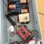
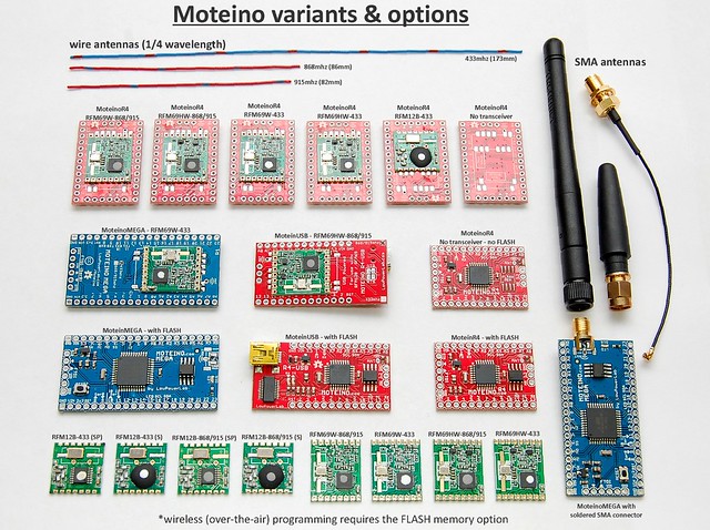
Why not bluetooth or wi-fi? They are getting low power and small too!
This is an area I have not fully discarded yet because I have not fully investigated yet. I like bluetooth but from all I know it requires pairing and won’t allow the distributed topology I’m looking for. So at least for now bluetooth is ignored. Wifi is a different story because it can hook into the home wireless wi-fi directly. It may make sense at some point or could be useful in certain applications. Adafruit and others have done a nice job integrating the CC3300 which is small, but unfortunately not so affordable, it’s about a magnitude more in price compared to RFM69 type radios. Also wi-fi is 2.4ghz which can get crowded with lots other devices using that band. I think I’ll wait for a while and hopefully price goes down too.
How about Xbee/Zigbee?
Not much to say here except my very first experiments were with XBees which were about half the range of RFM12B and about 4X the price and power consumption was not nearly ideal. Quickly became obvious this is not the way to go.

Fun fact: on the side is a user submitted photo in which he is testing a Moteino+RFM69 with tweaked RFM69 Lib settings for low bitrate/bandwidth and tweaked antenna to achieve an impressive 1.75Km range. This is fantastic and it means Moteinos are great for long range telemetry where bluetooth, wifi and other alternative technologies would be impossible to use and cost prohibitive. When I get stories like these about my product this makes my day. The full story and details are in the forum.

The choice of RFM69
So I’ve gone from RFM12B (which is still supported on all Moteinos) to RFM69 (W and HW). The reasons are many, and it worked out as a great trasceiver, affordable, and the RFM69 library I’ve created for it has become very widely used. Meshing is also possible for special applications. But in most cases meshing is not needed because by tweaking the settings, ranges of over a mile is achievable. The out of box RFM69 lib settings will give you several hundred meters in open air and should easily cover a 1 acre typical residential property/home. By contrast RFM12B could barely get from one end to the other in my home, with dead spots and dropped packets, unless I seriously decreased the bitrate. It’s also the right size, fits perfectly on the belly of all Moteinos and is the right price. The end product is a very compact node that can fit in almost anything, can be easily powered from a range of sources, and doesn’t require twisty weird assembly and microscopical soldering to bring it to life.

Design for manufacture

This is very important if anything you make is ever meant to scale. I see a lot of projects that are cool, but have more of an artisan feel to them, and in terms of making 100 or 1000 of them, it would require an army of people or countless hours to solder and custom fit/bend/twist/test. I hope the THP judges will see these issues and take them into account when judging between the good and great THP semifinalists. PCB making is affordable and anybody can do it with all the open/free PCB layout programs out there, but once you move from individual boards to panelized designs that need to be assembled into a pick and place it’s a whole different story, and a lot more things come into play. EEVBlog and others have done a good job explaining some of the challenges of designing for manufacture. This factor alone will make the difference between a good or bad design in the long run. With Moteino I tried to think of manufacturability from the start. I knew if my design was bad it would never get past a revision or two and nobody would want it. If it was good then I would eventually end up requiring machine assembly and rapid testing. Currently all Moteinos are assembled on my new real pick and place and reflowed in a real reflow oven. Then they are bootloaded and tested manually using a jig I made for them similar to this. It goes very fast but it was a long journey to get here, nevertheless quite rewarding and fulfilling one.

That’s all dear reader, have a nice day/evening/night/morning wherever you might be.


Meteor + React Native. Learning from Experience.

$
0
0

For close to two months now I’ve been working nearly exclusively with React Native. We use Meteor at Differential to build powerful web and mobile apps but most of these mobile apps are Cordova.

However, due to the needs of our client a hybrid app wasn’t going to suffice so we started exploring the possibilities and decided to move forward with React Native – both our team and theirs have a lot of experience with Javascript so it made sense.

The experience has been enlightening, I personally have been working with Meteor exclusively for 3 years, so I haven’t had too much exposure to the greater Javascript community. This was a great time to learn some new tools.

The process has been extremely interesting, full of ups and downs and new challenges daily. I wanted to walk through some of the challenges I’ve found, coming from a Meteor background, while working with React Native.

Challenge #1: No more user accounts

Meteor has a strong accounts system system built into the platform. On both the client and the server. Unfortunately, we don’t have that convenience in React Native.

If you’re used to using Meteor.user() to determine what screen to show a user in your web app, you’ll have to do some new thinking on your React Native app. I struggled with this at first, Meteor had just made it so easy, but it’s not too hard to do once you let go of the ease that Meteor.user() brings.

The same goes for the other conveniences that Meteor’s account system provides, they just don’t exist in React Native, so you’ve got to roll your own.

To accomplish this we’re using React Native’s AsyncStorage (which serves the same purpose as localStorage)

Challenge #2: No out of the box data reactivity

Meteor.user(), CollectionName.find(), CollectionName.findOne() are all reactive data sources in Meteor. You don’t have to do anything special to set that reactivity up – it just works out of the box. It’s a great experience…

but it doesn’t work out of the box in React Native. You’ve got to listen to events in the React Native app and handle your own reactivity. Again, once you get past just how easy it was while working in Meteor, you can roll your own implementation and it works.

Compared to Meteor there are just a few more steps involved. Not only do we have to subscribe but also how to listen and react to changes in data.
Reactive data in React Native

Challenge #3: Data Interaction

This experience has gotten much easier since my original draft of this post. We’re usingHarrison Harnisch’s node-ddp-client npm package to handle our DDP connection. Behind the scenes it’s using minimongo-cache to manage the collections. This provides a similar experience to that of Minimongo that comes with Meteor.

Like I said before, you have to roll your own reactivity, but at least you can use very similar (or the same) queries on both the client and server. We’ve found this to work for our needs so far.

Interacting with data via minimongo-cache

Side note: Checkout out Harrison’s lighting talk where he covers the ddp-clientpackage. He’s also got a repo that serves as a good starting point.

Learning from Example

I learn best by seeing real world examples so I wanted to provide a resource that could serve as an example for how we’re working through the challenges I outlined above.

I’m working on a project to match the Meteor Todos Example one to one in features in React Native so you can compare what writing a React Native app looks like with anearly stock Meteor app. The React Native app communicates via DDP with the web app and has (eventually) all the same functionality.

I encourage you to check it out, fork it, and play around with it. Let me know what your thoughts are and ways I could improve things – I’m certainly still figuring this all out.

Here’s the repo: https://github.com/spencercarli/meteor-todos-react-native-2


remotework.in – React and ES6 by example Meteor.js

$
0
0

remotework.in – React and ES6 by example

If you’ve followed the news about Meteor 1.2 you may came across React.js and ECMAScript 2015 (formerly ECMAScript 6) which will play a huge role in the 1.2 release and the future of Web development in general.

Today I want to show you a project I’ve started a few days ago which is open source and should make it easier to get started with Meteor, ES6 and React.

I could post some code snippets here and go through the code but I think that there are already some great tutorials out there (see “Additional Resources” below) which just do that.

I read a lot of source code on GitHub and I think that reading others source code is a great way to learn some new patterns and concepts. It’s even better if you can play with the application in production so you can see what action on the site triggers what functionality in the code.

So today I want to show you the project remotework.in. The Source Code can be found on GitHub.

Bildschirmfoto 2015-09-08 um 07.19.33

What is this project about?

As a freelancing Meteor developer I often use Platforms such as Upwork, Elance,Freelancer and We Work Meteor (which is an awesome platform if you want to find Meteor related jobs).

However, I’m always looking to find other JavaScript related jobs as well. I really liked the “We Work Meteor”-Approach of an easy job board where you just see the jobs and can contact the author of the job directly via Mail. But I wanted a Platform where every job can be posted (not just Meteor related jobs).

As I was already digging into ES6 and React I thought that it is time to start a project to create a remote job board with the help of those two new technologies to learn something along the way. So I started working on remotework.in / GitHub Source Code.

The functionality

The whole development process was focused on the creation of an easy to use job board.
There are no sign-ups or sign-ins for anyone. Just post a job or search for a new job. That’s it.

As a job poster you just enter the information about your job offer and hit save.
After that you get an E-Mail right into your inbox.
This E-Mail contains three links.
One to activate your job posting (after that it’s activated and will be visible to others), a second to edit your job posting and a third which makes it easy to remove your job posting. You should keep this E-Mail as it’s the only way to edit / remove the job posting later on.

As a job seeker you just browse through the jobs or search for specific jobs (the title and description of the job will be searched with the help of the MongoDB fulltext search).
Just click on the E-Mail Address and contact the job author if you think the job suits you.

The source code

Here’s the source code to the project. Feel free to send me sone PRs so we can improve it together.
You may look through the commits to see the history of the projects creation.

One thing at the end

I would be happy if you could maybe spread the love and share the job platform so that we can stress test it (if you know what I mean). :-)

Additional resources

Here are some blog posts about ES6, React and Meteor. You should definitely read them if you want to dig deeper into these topics.


ANALYSING 433 MHZ TRANSMITTERS WITH RTL-SDR

$
0
0

ANALYSING 433 MHZ TRANSMITTERS WITH RTL-SDR

RTL-SDR is a good addition to the arsenal of any hardware geek and this holds true for hardware security researchers too. Recently I did a talk at HITB Amsterdam (http://www.slideshare.net/yashinm/sniffing-the-airwaves-with-rtl-sdr) where I explained how the RTL-SDR was useful and how it can be leveraged for security applications.  With this blog post I intend to demonstrate how the RTL-SDR can be used to sniff 433 Mhz transmitters. These are pretty cheap and can be found in a lot of appliances including alarm sensors. This post is also intended to be an intro to RTL-SDR usage. I suggest you get Kali linux (1.0.6>) on your system as it has most of the dependencies required for this demo.

To show the capture of data and to simulate a transmission I’ll be using a FS1000A 433 mhz transmitter along with a Teensy to control it. These use ASK modulation.

IMG_20140618_162410-300x225

The code I used to transmit “1″ every 2 seconds:

#include <VirtualWire.h>
char *controller;
void setup() {
 pinMode(13,OUTPUT);
vw_set_ptt_inverted(true);
vw_set_tx_pin(2);
vw_setup(4000);
}

void loop(){
controller="1" ;
vw_send((uint8_t *)controller, strlen(controller));
vw_wait_tx();
digitalWrite(13,1);
delay(2000);
digitalWrite(13,0);
delay(100);
}

Initially to check whether the transmitter is working correctly I used gqrx (https://github.com/csete/gqrx). It’s a SDR receiver implemented in GnuRadio and is very useful for tracking down and recording signals. The following spike is obtained every two seconds:

centre

This tells us that the transmitter is working fine . To get a good look at the signal being generated we can use rtl_sdr combined with baudline (http://www.baudline.com/download.html). rtl_sdr is a tool that comes with the rtl-sdr package (rtl_sdr is the tool and rtl-sdr is the collection. For more info: http://sdr.osmocom.org/trac/wiki/rtl-sdr). It outputs raw I/Q data. Baudline is another useful tool that can be used to visually understand signals. The following command will pipe the output of rtl_sdr to baudline for analysis:

rtl_sdr -f 433920000 -s 1000000 – | baudline -reset -samplerate 1000000 -channels 2 -format u8 -quadrature -stdin

baudline  -F1- FFT=2048 sample_rate=1000000 Hz=1X timebase=1X  _020

In most cases baudline can help you determine which modulation the transmitter is using and can be a good addition to gqrx and other receivers.

Another tool that we haven’t touched yet (at least not directly) is GnuRadio. Any serious work with software defined radio will probably include GnuRadio as it has support for a large number of devices such as the HackRF, RTL-SDR, USRP and the Funcube dongle. GnuRadio works with a block architecture: signal sources, converters, amplifiers and more are all blocks. Devices from which there’s an output of data is known as sources and blocks to which there’s only input are known as sinks. The source block for RTL-SDR gets installed when you install the rtl-sdr block. I’m using GNURadio 3.7 on Ubuntu.

To get started, open up GNU Radio Companion and from the Source section drag the “RTL-SDR” Source to the main work area.

Double click on the newly created source and set frequency as 433920e3 (433.92 Mhz). Change the variable block samp_rate on the right so that it’s value is 96e3 (96k). Since we need to hear the transmissions we’ll need an audio sink. Choose Audio Sink from the Audio section and drop it into the work area. In the sample rate section of the sink enter “int(samp_rate)”.

-untitled - GNU Radio Companion_023

There’s a slight problem as the output of the RTL-SDR source is a complex data type and the Audio Sink accepts real datatype. GNURadio has you covered for this too! Choose a complex to real convertor from the Type Convertor section.

Join the blocks by clicking on the Out of the source and then the In of the Complex to Real convertor. Do the same for the sink. Click on the Execute button on the top of the GRC and you’ll begin to hear small pips of data every two seconds.

Now that we can access the audio stream through GRC we’ll also need to see the actual signal wave. To see the peaks in radio traffic we’ll  use a FFT sink and for saving to file, a wav file sink. Make sure you set the filename that you want to save to and the bits per sample as 8. Your GRC graph should look like this:

You can open up the file in Audacity and see the signal wave in it:

Note:Sometimes when you open up audacity you’ll notice that there’s no signal in it. This happens because when a flow graph is terminated suddenly, the wav block may not write to the file correctly. For this purpose we’ll add a dropdown box that’ll allow you to switch between the file and /dev/null. Once the recording is done you should switch to /dev/null before closing. This will ensure that the file has been written properly.

Here’s how file choosing was implemented:

However since this is a 433 mhz transmission we already have a very easy to use tool by merbanan (https://github.com/merbanan/rtl_433) that actually converts the radio signals back to data.  As the transmissions aren’t from any weather station or temperature sensor we will have to run rtl_433 with the analyse option set.  It can be clearly seen that the data exists after a sequences of “0″s.

rtl_433 -a

4331

If we change the transmission from the Arduino to a “2″ instead of “1″ we get:

4332

Stay tuned for more posts on radio hackery!


Hardware Security Resources

$
0
0

Hardware Security Resources

Here are some whitepapers and blogpapers that should help you get started/learn more about hardware security. I’ve divided the page into divisions for easier viewing.

I’ll keep adding to the list when I remember any other sites/papers that I refer to. Please let me know of any mistakes/suggestions down in the comments!

Blogs/Websites

/dev/ttys0 blog 

cybergibbons

IOActive

Natashenka’s blog

Travis Goodspeed’s blog

Michael Ossman’s blog

Hackaday

Bunnie Huang’s blog

Adafruit

Sparkfun Blog

Lacklustre Blog

Dangerous Prototypes

Adam Laurie’s blog

SRLabs

Xipiter

Chip Whisperer Documentation

Spritesmod blog

Whitepapers/Required reading

General hardware reverse engineering/ attacks

Intro to hardware hacking

Reversing a vacuum cleaner

Joe Grand’s talk on Tools of the Hardware Hacking Trade

Craig Heffner’s blogpost on identifying and using serial ports

Reverse engineering a DTV converter

Reverse engineering a router

Joe Grand: Current state of hardware hacking

LayerOne talk on hardware reverse engineering [Check the other parts too]

HW RE course at Rensselaer Polytechnic Institute. Course Material

A collection of posts by CyberGibbons on wireless burglar alarms[CyberGibbons]

Reverse Engineering a Furby

Recon talk on hardware RE

Hardware hacking for software people – Stephen Ridley

Using Shikra for UART/JTAG debugging

Reversing a home controller

Breaking a Fingerprint protected HD

Breaking a Fingerprint protected USB

Hijacking Drones

Bluetooth Low Energy

Bluetooth: With Low Energy Comes Low Security

Bypassing Passkey Authentication in Bluetooth Low Energy

NIST document on Bluetooth security

Outsmarting Bluetooth Smart

How Smart is Bluetooth Smart

Understanding BLE advertisement packets

Understanding BLE advertising packets

Introduction to BLE

Reverse engineering a BLE bulb

Bluetooth 2.0/3.0

NIST document on bluetooth security

Security in Bluetooth

Bluetooth threats (old ones)

Security Weaknesses in Bluetooth

Sniffing Bluetooth using Ubertooth by Dominic Spill

Side channel attacks

Side Channel Attacks [Good intro to SCA]

Improved Higher-Order Side-Channel Attacks with FPGA Experiments

Power Analysis for Cheapskates – Colin O’Flynn

Video for the above talk: https://www.youtube.com/watch?v=i27NiVuWmhE

ChipWhisperer documentation/ Good info on SCA

Glitching/Fault Injection

Intro to Fault Injection attacks

Writeup of how the PS3 hypervisor was attacked using glitching

Low Cost Attacks on Tamper Resistant Devices

The Sorcerer’s Apprentice Guide to Fault Attacks

Clock glitching tutorial

Vcc glitching

Fault attacks on secure chips: from glitch to flash

Glitching for noobs

Practical Analysis of Embedded Microcontrollers against Clock Glitching Attacks

Practical Attacks against the MSP430 BSL

Fault injection attacks and defences

Security Failures in Secure Devices

Firmware analysis

Firmware Analysis Writeup

Belkin WPS PIN reversing

DLINK DIR980L Firmware reversal

DLINK security failures

Reversing DLINK WPS PIN algorithm

RFID/NFC

New Attacks against RFID

RFID Security: Attacks, Countermeasures and Challenges

Attacks on RFID Protocols

NFC Attack Surface

Practical Relay Attack on Contactless Transactions by Using NFC Mobile Phones

RF Hackery

Good writeup on RF security in general

SDR attacks on smart homes

KillerBee Zigbee attack framework

Exploiting ZigBee

Penetration of ZigBee-based wireless sensor networks

Ghost-in-the-Wireless: Energy Depletion Attack on ZigBee

Decoding Train Announcement Boards

Deciphering mystery signals from a helicopter

Decoding radio controlled bus stop displays

OpenSesame attack on garage door openers

Remotely trigger doorbells

SDR tutorials by Mike Ossman

Hacking a Lego Car using HackRF

GSM/UMTS

Attacking SMS

GSM sniffing [CCC talk by Karsten Nohl]

A practical attack against GPRS/EDGE/UMTS/HSPA mobile data communications

UMTS MITM

Privacy through Pseudonymity in Mobile Telephony Systems

Location leaks on the GSM air interface

Decrypting GSM phone calls

Rooting SIM cards

Automotive security

Charlie Miller/Chris Valasek comprehensive paper on automotive security

Good writeup on CAN bus packets

Hacking into a Vehicle CAN bus (Toyothack and SocketCAN)

Books to read:

Hacking the XBox by Andrew “bunnie” Huang

http://www.amazon.com/Introduction-Hardware-Security-Mohammad-Tehranipoor/dp/1441980792

http://www.amazon.com/Android-Hackers-Handbook-Joshua-Drake/dp/111860864X/ [Good section on hardware hacking]

People to follow on twitter

Mike Ryan

Felix Domke

CyberGibbons

Jay Beale

Justin Searle

SpritesMods

Samy Kamkar

Charlie Miller

Dangerous Prototypes

Joe Grand

/dev/ttys0

Oona Räisänen

at1as

Travis Goodspeed

Michael Ossmann

Chris Valasek

Xipiter

Stephen Ridley


Particle Guides, Tutorials, Projects, Links

$
0
0

Love making things with the Particle Core and Photon? Just getting started? Either way, this page should have some links with guides, tutorials and a bunch of existing projects out there that might inspire your development adventures with the cloud connected microcontroller!

Getting Started

Useful Links

Interesting Project Tutorials

Using Particle Core with Node

Troubleshooting

Community

Looking to find the LightBlue Bean community? The best spot appears to be their Particle forums.


Where to buy electronics in Toronto?

$
0
0

Selected US/international vendors that serve Canada.

Presented in no particular order:

  1. Digi-Key. Canada-specific home page 
    •The best service. A very complete parts line-up.
  2. Mouser. Canada-specific home page 
    •Good service. A very complete line-up, probably not as many as Digi-Key, but close.
  3. Allied. Home page–you have to change the country yourself 
    •I’ve not ordered from them, but I have received a good recommendation.
  4. Arrow. The North American division 
    •I recently ordred one of their own products. Surprise extra charges from Fedex came a week later.
  5. Newark (Element 14). Canada-specific home page .
    •Full line distro, I have no recent experience with them.
  6. Sparkfun .
    •I have not ordered from them. Several Canadian suppliers distribute SparkFun items.
  7. AdaFruit .
    •I have not ordered from them. Several Canadian suppliers distribute AdaFruit items.

Canadian sources.

Presented in no particular order (the numbers exist only for reference), I’ve tried to condense all the important information into a couple of lines. I certainly have not ordered from all of them!

  1. dipmicro , Niagara Falls.
    •Web-based initially, now, as of mid 2014, a retail store has opened in Niagara Falls, no phone orders. They sell new components and some boards, e.g. Chinese Arduino clones.
  2. Spikenzie , Montreal.
    •Sell new components and many boards: AdaFruit, SparkFun and others. A few ICs only.
  3. Electrosonic .
    •One of the best things about taking EE at the University of Toronto when I did was being able to walk over to Electro Sonic at lunch! Alas they moved long ago, and they no longer list anysemi companies on their linecard. Still OK for passives, tools, instruments and Hammond cases. Despite their stock being maintained in the US I still think of them as Canadian.
  4. Active 
    •Retail stores in Toronto, Ottawa, Winnipeg, Edmonton and Calgary (no longer Vancouver). More or less full product line.
  5. Sayal , Toronto.
    •Several retail outlets in Southern Ontario. Largely surplus stock. Terrible web site with almost no prices!
  6. Cana Kit , Vancouver.
    •Sell kits and boards: their own designs as well as SparkFun and others. No components.
  7. RP Electronics , Vancouver.
    •Retail location in Vancouver. Failrly full line from books to components, to test equipment.
  8. Lee’s Electronics , Vancouver.
    •Retail location on Main in Vancouver. Wide variety of items, including some Hammond boxes. Poor web site.
  9. Creatron , Toronto.
    •Retail store on College. Wide range of parts and assemblies up to modern boards such as the Lilypad series and Raspberry Pi.
  10. Proto Advantage , Hamilton.
    •Mostly breadboarding package adapters, but Arduinos also carried, especially the Netduino.
  11. RobotCraft , London, ON.
    •No retail store. Components and boards related to robotics mostly.
  12. A-One Counterparts , London, ON.
    •Retail store. Components and boards, including Sparkfun and Adafruit. (Poor site with broken links in menu.)
  13. RobotShop , Mirabel, PQ.
    •No retail store. Components and boards related to robotics mostly.
  14. Solarbotics , Calgary.
    •No retail outlet. From BEAM robotics to solar to Arduinos…
  15. B&E Electrnics , Calgary, Regina, Saskatoon.
    •Retail outlets in all three cities. Slanted towards industrial electronics. Refreshingly they only ship to Canadian addresses.
  16. Canada Robotix  Markham, ON.
    •Retail outlet. Roombas to Arduinos…
  17. ABRA Electronics , Montreal.
    •Montreal retail location. Quite a wide range of parts and boards.
  18. A1 Electronic Parts , Toronto.
    •Retail store near the bottom of Hwy 427. Stock is a mix of surplus parts up to modern boards such as Raspberry pi.
  19. Interior Electronics, Kelowna & Burnaby plus Queale Electronics , Victoria.
    •More oriented towards repair and maintenace of equipment, these stores are still sources for passive components and test equipment.
  20. BC Robotics , Nanaimo BC.
    •Arduino; R-Pi; Beagle; Adafruit; a bit of Spikenzie. Strange that one learns about a (the only?)local electronics supplier from somebody at a bus stop in another city! It did help that I was on the way to the Vancouver Mini Maker Faire…
  21. Mikronauts , Lower Mainland, BC.
    •A supplier of boards and kits of their own design. Aimed largely at the education market, their microcontrollers are heavily Propeller based.
  22. Voltatek Electronics , Montreal.
    •No storefront. Arduino, Raspberry pi, Beaglebone as well as general parts and prototyping supplies.
  23. Main Electronic Supplies , Vancouver.
    •Arduino clones, good selection of power supplies and some other test equipment, NTE TV service components.
  24. Meistertech Solutions , Southern Ontario (Aylmer).
    •An interesting collection. Mostly discrete parts aimed at repair and refurbishment. A good place to look for a replacement bulb or an audio grade capacitor.

If you are in the Toronto area, a site which serves as a resource to local suppliers can be found at Karma Laboratories 

Toronto Electronics Retailers

A-1 Electronic Parts

http://a1parts.com

196 North Queen Street, Toronto, ON

(416) 255-0343

I haven’t been here but I’m told it’s like Active Surplus.

Above All Electronics

602 Bloor St W, Toronto, ON

(416) 588-8119

It’s been a while but I remember this place being sort of between Active Surplus and Supremetronics in selection.

Active Surplus

http://activesurplus.com

347 Queen Street West – 2nd floor, Toronto, ON

(416) 593-0909

Carries major electronics components plus cheap, quirky surplus items. Everything sold “as is” so it may be hard to find the exact item you’re looking for since they don’t offer datasheets or specs. 20-30% of inventory turns over often so wander its aisles every month or so.

Creatron

http://creatroninc.com

349 College St, Toronto, ON

(647) 349 9258

Carries almost all of the major electronics components in very neat organized baggies on the wall or bins in the back. This is one of the few places you’ll be able to pick up an Arduino or Arduino-related hardware in Toronto. Carries a small collection of the kits you might find at Sparkfun or the Makezine store (listed as online retailers below) so Creatron is definitely worth checking out if you don’t want to wait for shipping, plus the prices are comparable.

Note: As of mid-2014, Creatron opened a new store at Vic Park and Sheppard and moved their original downtown store to 349 College St (at Augusta Ave) from previous location at 255 College St (at Spadina Ave).

Note: The new downtown location is smaller so doesn’t stock everything that Creatron sells. They will bring items down from their better stocked suburban store – just give them a call to ask.

Creatron – Scarborough store

https://www.creatroninc.com/

3127 Sheppard Ave. East, Scarborough, Ontario, Canada M1T 3J7

(416) 977 9258

Opened mid-2014. Same owners as the Spadina Creatron, but they tend to have a wider range of stock (plus Lawrence the owner is based there and he’s a great resource on electronic design if he has time).

Sayal

http://sayal.com

3791 Victoria Park Ave – Units 1-5, Toronto, ON

(416) 494-8999

Additional stores in Mississauga, Vaughan, Cambridge, and Burlington. Never been there but apparently has a lot bigger selection than Supremetronics.

Supremetronic

290 College St, Toronto, ON

(416) 922-1158

Carries a wider range of electronics components than Active Surplus but not as much as Creatron. Specs are marked on most bins.

Note: Supremetronic is part of Home Hardware and is located in the basement of this Home Hardware location.

Toronto Hardware & Misc Retailers

Brafasco (CTF Supply)

http://brafasco.com

31 Parliament St, Toronto, ON

(416) 364-9191

If you’ve got a tricky screw head (tamper-resisant ones) they might have the right screwdriver for you.

LaserGlow

http://laserglow.com

5 Adrian Ave, Toronto, ON

(416) 729-7976

Need lasers for your next GRL Laser Tag project? Special infrared lasers? Email the folks there (or ask for Justin) and they can work with you to get you the right laser. They don’t carry everything in stock so give them at least 2-3 weeks notice first so they can order it from their supplier.

Lee Valley

http://leevalley.com

590 King Street W, Toronto, ON

(416) 366-5959

Two other locations in Toronto and online shopping available. Lee Valley is kind of a throwback to the 70s and 80s since Lee Valley is really famous for their catalouge sales. But the things they stock are the best of the best.

Rotblott’s Discount Warehouse

http://rotblotts.com

443 Adelaide Street W, Toronto, ON

(416) 703-0456

This is a go-to destination if you work in the film industry. They have a random assortment of hardware and office supplies, along with surplus items. But my favourite thing is something called “Gaffers tape” which is a slightly more expensive tape than duct tape, but it doesn’t leave any sticky residue behind when removed.

Toronto Tool Library

http://torontotoollibrary.com/

1499 Queen St W, Toronto, ON, M6R 1A3

(647) 965-5604

Non-profit tool rental service providing everyone with access to home repair tools and power tools.

As a member of the Toronto Tool Library, members signout tools for both their home and community initiatives. Whether you are hanging a picture or renovating a community park, the Toronto Tool Library offers a rangeof equipment for your project as a low-cost, resource sharing and space-saving alternative to purchasing and owning tools. Non-profits and charitable organizations will also enjoy special membership rates.

Online Retailers

Adafruit Industries

Adafruit has done tons for the maker community. Easy website to shop on with tutorials for both individual electronics components and their own custom kits like the MintyBoost. (U.S. based so be careful of customs.)

Brickyard Ceramics & Crafts

Closest retailer of Amaco’s “Friendly Plastic” (polymorph plastic) – they are actually in the same building! If you have a GST account, call them directly and they can offer a 30% discount. (U.S. based so be careful of customs; and if you want next day or 3 day shipping, be prepared to pay $80, otherwise only $15 for regular 5-7 day standard shipping.)

Digikey

U.S. based company that offers a Canadian retail portal; Prices are in CAD$ and customs/duty charges are already worked in so you won’t be surprised with a $30 FedEx bill for a $10 purchase. Shipping is cheap and prompt (2-5 days). Unless you know the exact part you’re looking for or have good specs, download a catalog for browsing.

Inventables

All sorts of interesting and inspiring materials here. Get ready to browse this site for an hour!

Maker SHED

A few years ago, the web store companion to the iconic Make magazine only really carried kits but today is a formidable place for getting Arduinos, Arduino accessories, and general electronics supplies. They even carry more one-off items such as Chumby Guts, Shapelock moldable plastic, and Pixel Qi screens.

Newark

Alternative Canadian retail portal. Consider opening a FedEx, UPS, etc account so you have more shipping options (including guarenteed next day delivery) but I’ve never had to wait more than 2 days for my packages. Offers a nice visual “selector guide” section.

Robot Shop

Not too sure where exactly they are based but there’s a Canadian retail portal; Prices are in CAD$ and customs/duty charges are already worked in. Haven’t bought anything robotics-related from them yet but I have purchased Flexinol wires from them – and they may be the only place in CAD$ that you can find them.

Sparkfun

Super user-friendly electronics shopping. Very visual and easy to understand. Carries lots of Arduino-related products, including the LilyPad. (U.S. based so be careful of customs.)

Sundance Solar

Retailer of solar panels and many other solar related items. User friendly product descriptions keeps you from shopping in the dark. (U.S. based so be careful of customs.)

Upverter

Upverter is not a retailer but they do have an option to order PCBs from the designs you create in their software.


install the Guest Additions in VirtualBox

$
0
0
sudo apt-get install build-essential linux-headers-`uname -r` dkms

ARMING A BREADBOARD — EVERYONE SHOULD PROGRAM AN ARM

$
0
0

ARMING A BREADBOARD — EVERYONE SHOULD PROGRAM AN ARM

I’m always a little surprised that we don’t see more ARM-based projects. Of course, we do see some, but the volume isn’t what I’d expect given that low-level ARM chips are cheap, capable, low power, and readily available. Having a 32-bit processor with lots of memory running at 40 or 50 MIPS is a game changer compared to, say, a traditional Arduino (and, yes, the Arduino Due and Zero are ARM-based, so you can still stay with Arduino, if that’s what you want).

A few things might inhibit an Arduino, AVR, or PIC user from making the leap. For one thing, most ARM chips use 3.3V I/O instead of the traditional 5V levels (there are exceptions, like the Kinetis E). There was a time when the toolchain was difficult to set up, although this is largely not a problem anymore. But perhaps the largest hurdle is that most of the chips are surface mount devices.

Of course, builders today are getting pretty used to surface mount devices and you can also get evaluation boards pretty cheaply, too. But in some situations–for example, in classrooms–it is very attractive to have a chip that is directly mountable on a common breadboard. Even if you don’t mind using a development board, you may want to use the IC directly in a final version of a project and some people still prefer working with through hole components.

THE 28 PIN SOLUTION

One solution that addresses most, if not all, of these concerns is the LPC1114FN28 processor. Unlike most other ARM processors, this one comes in a 28 pin DIP package and works great on a breadboard. It does require 3.3V, but it is 5V tolerant on digital inputs (and, of course, a 3.3V output is usually fine for driving a 5V input). The chip will work with mbed or other ARM tools and after prototyping, you can always move to a surface mount device for production, if you like. Even if you are buying just one, you should be able to find the device for under $6.

I recently wanted some breadboard setups for students. I did end up make a simple PCB that plugs into a breadboard, but looking back the simple circuit would have worked just as well placed directly on a breadboard. Here’s what you need:

  • An LPC1114FN28
  • A 3.3V power supply
  • A 3.3V or 5V USB to serial cable or adapter
  • One or two 220 ohm resistors (not absolutely necessary)
  • An LED and suitable resistor (optional)
  • Two 0.1uF capacitors (not absolutely necessary)

If you have a USB cable that puts out 3.3V, you can probably drive the chip directly with that. Otherwise, you can use an LD1117-3.3 or an LM7833. A bench supply or one of those cheap power supplies that plugs into a breadboard will work too. Just remember, the chip needs between 1.8V and 3.6V to operate.

BUILDING THE HARDWARE

The circuit is so simple, you almost don’t need a schematic. Here’s one anyway:

Breadboard

One reason that this works so well is the chip has a built-in serial bootloader. If you short the PIO0_1 pin to ground and reset the chip, you can easily upload a program to the device. You could probably get away with just shorting both pins to ground (they are internally pulled up). However, I like to put a small (220 ohm) resistor in series in case software is driving the pin as an output for some reason.

Of course, the jumpers (BOOT and RESET) and connectors in the schematic can just be breadboard wires if you don’t want to mount actual pins. The USB “connector” assumes that pin 2 is ground, pin 3 is the PC’s receiver and pin 4 is the transmit (that is, the LPC1114 talks on 16 and listens on pin 15). If that doesn’t match your cable or RS232 converter, change it as needed.

You may also want to adjust the value of the resistor depending on your LED, but you aren’t making a flashlight, so any value that will get a visible glow ought to be fine (or, omit it completely if you don’t want to blink an LED). If you are a real minimalist, you could dump the 220 ohm resistors, too. The capacitors help decouple your power supply, but breadboards have a good bit of capacitance already and if you have a clean supply, you might not need those either.

So if you have a breadboard and a USB to serial adapter, you could build the bare bones version of this for about $6 and maybe break the bank at $15 if you had to buy everything. Of course, if you have another ARM programmer/debugger that you want to use, that could be wired up instead of the USB cable. But I’m guessing if you have that kind of hardware, you’ve already solved your breadboarding problem.

breadboard1Here’s my (almost) bare bones version:

Not pretty, but effective. I used a switch for the reset and just a wire for the boot jumper. The LED has an internal 5V dropping resistor, but works fine at 3.3V (and I dropped the other two resistors and the capacitors). To work through the software example below, you’ll either need another LED connected to pin 1, or you can just lift up the connection on the breadboard and repurpose the LED. Be aware though: The mbed code assumes you have an LED connected to pin 14 and will blink it if it finds run time errors. If you move the LED you could have an error and won’t get an indication.

SOFTWARE

You can use any ARM tool chain that can generate code for the LPC1114. There are plenty to choose from, but I’m going to assume you are just getting started, so let’s use the mbed web site. I’ve covered how to program using mbed before, and you might want to check out the video below for that walk through.

Here’s a quick summary of the steps you’ll need to take:

  • Go to http://developer.mbed.org
  • Create an account if necessary and log in
  • Click on Platforms and find LPC1114FN28 (or go directly to the page)
  • Click Add to Your mbed Compiler–if you see a button that says Remove, you’ve already done this
  • Now head to the project page and import the project
  • Compile the project and download the BIN file

Once you have the BIN file you’ll need to upload the program via your serial port. I’m going to use a utility called lpc21isp to do that. You can usually find this in your Linux repository, and there is a Windows version available, too. If you just hate the command line, you can always use FlashMagic or the official NXP Windows downloader. There are some GUI front ends for lpc21isp, too, but it is simple enough to use the command line.

The file you’ll download from the mbed website will be named HaD1114Demo_LPC1114.bin unless you changed it (I’ll assume it is in directory /tmp). You also need to know the name of your serial port (e.g., COM1 or /dev/ttyUSB8). The last thing you need to know is roughly what clock frequency the CPU is using. In our case it is 48MHz. Here’s the command line:

lpc21isp -verify -bin /tmp/HaD1114Demo_LPC1114.bin /dev/ttyUSB8 115200 48000

You want to engage the boot jumper and reset the chip either right before or right after executing that command line. The 115200 sets the baud rate and the 48000 is required so the software can sync with the bootloader.

Once you get a successful download, lpc21isp will tell you it is launching the new code. Don’t believe it — It isn’t doing anything yet. You’ll need to disengage the boot jumper and then reset the CPU again. If you prefer to do just a blinking LED, start a new project and that’s one of the boilerplate examples you can use in a new project.

INSIDE THE CODE

The code is simple. Just like the Arduino has a lot of helper library routines, mbed provides most of what you need to drive the devices on the CPU. There’s also an active community of shared libraries for external devices and example code. Here’s the simple code used for the demo:

1
2
3
4
5
6
7
8
9
10
11
12
13
14
15
16
#include "mbed.h"
PwmOut myled(dp1);
int main()
{
 int i,j;
 while(1)
 {
 for (j=0;j<2;j++)
   for (i=0;i<1000;i+=10)
    {
    float pwm=i/1000.0;
    myled=j?1.0-pwm:pwm;
    wait(0.01);
    }
 }
}

The mbed library frequently makes use of floating point numbers. In the example code, the PWM range is from 0.0 to 1.0. The wait call uses seconds, so 0.01 is 10 milliseconds (there is a wait call that takes a millisecond value, by the way).

The j loop keeps track of even or odd passes so the PWM gets reversed on alternate passes. When j is zero, the PWM goes from 0 to 1.0. When j is not zero, the steps go from 1.0 down to 0. Each pass requires 100 steps (0 to 1000, counting by 10s) so the total time per pass is about 100 times 10 millisecond, or one second.

WHAT’S NEXT?

The mbed library is one place to start, and you can read its documentation online. If you are tied to the Arduino library, there is a port on Github (although I haven’t tried it). However, you can step up to bigger tools and even debugging when you are ready (there’s a good set of examples on Digikey’s eewiki, or you can keep using mbedwith your own IDE and debugger). If you want a quick rapid prototyping arrangement, this set up will easily run a pretty nice Forth, too. And if you are concerned that this isn’t really a hack, you could always chop the chip down to size literally (although we don’t recommend it).


SDR TUTORIALS FROM MICHAEL OSSMANN

$
0
0

SDR TUTORIALS FROM MICHAEL OSSMANN

If you’re just getting into software-defined radio (SDR) but you find some of the math and/or terminology a bit of hurdle, you could absolutely do worse than to check out these SDR tutorials by [Michael Ossmann]. While they’re aimed at people using his HackRF One tool (which we love), most of the tutorial videos are very generally applicable, and we realized that we hadn’t mentioned them explicitly before. Shame on us!

Ossmann focuses on SDR using the open-source GNURadio Companion GUI tool, which makes implementing a lot of cool SDR techniques as easy as dragging and dropping items into a flow diagram. If you want an overview of GNURadio or SDR in general, these videos are a must-watch.

In particular, we loved his entries on complex numbers and complex numbers in DSP because he goes through the whole rationale behind using imaginary numbers in radio work with a graphical presentation that helps add rationale to the otherwise slightly spooky math. Heck, watch these two even if you’re not interested in radio.

The newest entry, covering DSP filters includes a great hands-on introduction to finite impulse response (moving average) digital filters. We really like the practical, simulation-based approach presented in the video — it’s just perfect for a quick introduction.

So if you’re looking for a relatively painless way to get into SDR, grab yourself an RTL-SDR dongle, burn yourself aGNURadio Live DVD, and work through these videos.

POST NAVIGATION


超全!iOS 面试题汇总

$
0
0

作者:Job_Yang

之前看了很多面试题,感觉要不是不够就是过于冗余,于是我将网上的一些面试题进行了删减和重排,现在分享给大家。(题目来源于网络,侵删)

1. Object-c的类可以多重继承么?可以实现多个接口么?Category是什么?重写一个类的方式用继承好还是分类好?为什么?

答: Object-c的类不可以多重继承;可以实现多个接口,通过实现多个接口可以完成C++的多重继承;Category是类别,一般情况用分类好,用Category去重写类的方法,仅对本Category有效,不会影响到其他类与原有类的关系。

2. #import 跟#include 又什么区别,@class呢, #import<> 跟 #import””又什么区别?

答:#import是Objective-C导入头文件的关键字,#include是C/C++导入头文件的关键字,使用#import头文件会自动只导入一次,不会重复导入,相当于#include和#pragma once;@class告诉编译器某个类的声明,当执行时,才去查看类的实现文件,可以解决头文件的相互包含;#import<>用来包含系统的头文件,#import””用来包含用户头文件。

3. 属性readwrite,readonly,assign,retain,copy,nonatomic 各是什么作用,在那种情况下用?

答:

1). readwrite 是可读可写特性;需要生成getter方法和setter方法时

2). readonly 是只读特性 只会生成getter方法 不会生成setter方法 ;不希望属性在类外改变

3). assign 是赋值特性,setter方法将传入参数赋值给实例变量;仅设置变量时;

4). retain 表示持有特性,setter方法将传入参数先保留,再赋值,传入参数的retaincount会+1;

5). copy 表示赋值特性,setter方法将传入对象复制一份;需要完全一份新的变量时。

6).nonatomic 非原子操作,决定编译器生成的setter getter是否是原子操作,atomic表示多线程安全,一般使用nonatomic

4.写一个setter方法用于完成@property (nonatomic,retain)NSString *name,写一个setter方法用于完成@property(nonatomic,copy)NSString *name

答:

1
2
3
4
5
6
7
8
9
10
11
12
- (void) setName:(NSString*) str
{
[str retain];
[name release];
name = str;
}
- (void)setName:(NSString *)str
{
id t = [str copy];
[name release];
name = t;
}

5.对于语句NSString*obj = [[NSData alloc] init]; obj在编译时和运行时分别时什么类型的对象?

答: 编译时是NSString的类型;运行时是NSData类型的对象

6.常见的object-c的数据类型有那些, 和C的基本数据类型有什么区别?如:NSInteger和int

答:object-c的数据类型有NSString,NSNumber,NSArray,NSMutableArray,NSData等等,这些都是class,创建后便是对象,而C语言的基本数据类型int,只是一定字节的内存空间,用于存放数值;NSInteger是基本数据类型,并不是NSNumber的子类,当然也不是NSObject的子类。NSInteger是基本数据类型Int或者Long的别名(NSInteger的定义typedef long NSInteger),它的区别在于,NSInteger会根据系统是32位还是64位来决定是本身是int还是Long。

7.id 声明的对象有什么特性?

答:Id 声明的对象具有运行时的特性,即可以指向任意类型的objcetive-c的对象;

8.Objective-C如何对内存管理的,说说你的看法和解决方法?

答:Objective-C的内存管理主要有三种方式ARC(自动内存计数)、手动内存计数、内存池。

1). (Garbage Collection)自动内存计数:这种方式和java类似,在你的程序的执行过程中。始终有一个高人在背后准确地帮你收拾垃圾,你不用考虑它什么时候开始工作,怎样工作。你只需要明白,我申请了一段内存空间,当我不再使用从而这段内存成为垃圾的时候,我就彻底的把它忘记掉,反正那个高人会帮我收拾垃圾。遗憾的是,那个高人需要消耗一定的资源,在携带设备里面,资源是紧俏商品所以iPhone不支持这个功能。所以“Garbage Collection”不是本入门指南的范围,对“Garbage Collection”内部机制感兴趣的同学可以参考一些其他的资料,不过说老实话“Garbage Collection”不大适合适初学者研究。

解决: 通过alloc – initial方式创建的, 创建后引用计数+1, 此后每retain一次引用计数+1, 那么在程序中做相应次数的release就好了.

2). (Reference Counted)手动内存计数:就是说,从一段内存被申请之后,就存在一个变量用于保存这段内存被使用的次数,我们暂时把它称为计数器,当计数器变为0的时候,那么就是释放这段内存的时候。比如说,当在程序A里面一段内存被成功申请完成之后,那么这个计数器就从0变成1(我们把这个过程叫做alloc),然后程序B也需要使用这个内存,那么计数器就从1变成了2(我们把这个过程叫做retain)。紧接着程序A不再需要这段内存了,那么程序A就把这个计数器减1(我们把这个过程叫做release);程序B也不再需要这段内存的时候,那么也把计数器减1(这个过程还是release)。当系统(也就是Foundation)发现这个计数器变 成员了0,那么就会调用内存回收程序把这段内存回收(我们把这个过程叫做dealloc)。顺便提一句,如果没有Foundation,那么维护计数器,释放内存等等工作需要你手工来完成。

解决:一般是由类的静态方法创建的, 函数名中不会出现alloc或init字样, 如[NSString string]和[NSArray arrayWithObject:], 创建后引用计数+0, 在函数出栈后释放, 即相当于一个栈上的局部变量. 当然也可以通过retain延长对象的生存期.

3). (NSAutoRealeasePool)内存池:可以通过创建和释放内存池控制内存申请和回收的时机.

解决:是由autorelease加入系统内存池, 内存池是可以嵌套的, 每个内存池都需要有一个创建释放对, 就像main函数中写的一样. 使用也很简单, 比如[[[NSString alloc]initialWithFormat:@”Hey you!”] autorelease], 即将一个NSString对象加入到最内层的系统内存池, 当我们释放这个内存池时, 其中的对象都会被释放.

9. 原子(atomic)跟非原子(non-atomic)属性有什么区别?

答:

1). atomic提供多线程安全。是防止在写未完成的时候被另外一个线程读取,造成数据错误

2). non-atomic:在自己管理内存的环境中,解析的访问器保留并自动释放返回的值,如果指定了 nonatomic ,那么访问器只是简单地返回这个值。

10. 看下面的程序,第一个NSLog会输出什么?这时str的retainCount是多少?第二个和第三个呢? 为什么?

1
2
3
4
5
6
7
8
9
10
11
NSMutableArray* ary = [[NSMutableArray array] retain];
NSString *str = [NSString stringWithFormat:@"test"];
[str retain];
[aryaddObject:str];
NSLog(@”%@%d”,str,[str retainCount]);
[str retain];
[str release];
[str release];
NSLog(@”%@%d”,str,[str retainCount]);
[aryremoveAllObjects];
NSLog(@”%@%d”,str,[str retainCount]);

str的retainCount创建+1,retain+1,加入数组自动+1 3

retain+1,release-1,release-1 2

数组删除所有对象,所有数组内的对象自动-1 1

11. 内存管理的几条原则时什么?按照默认法则.那些关键字生成的对象需要手动释放?在和property结合的时候怎样有效的避免内存泄露?

答:谁申请,谁释放

遵循Cocoa Touch的使用原则;

内存管理主要要避免“过早释放”和“内存泄漏”,对于“过早释放”需要注意@property设置特性时,一定要用对特性关键字,对于“内存泄漏”,一定要申请了要负责释放,要细心。

关键字alloc 或new 生成的对象需要手动释放;

设置正确的property属性,对于retain需要在合适的地方释放,

12.如何对iOS设备进行性能测试?

答: Profile-> Instruments ->Time Profiler

13. Object C中创建线程的方法是什么?如果在主线程中执行代码,方法是什么?如果想延时执行代码、方法又是什么?

答:线程创建有三种方法:使用NSThread创建、使用GCD的dispatch、使用子类化的NSOperation,然后将其加入NSOperationQueue;在主线程执行代码,方法是performSelectorOnMainThread,如果想延时执行代码可以用performSelector:onThread:withObject:waitUntilDone:

14. MVC设计模式是什么? 你还熟悉什么设计模式?

答:

设计模式:并不是一种新技术,而是一种编码经验,使用比如java中的接口,iphone中的协议,继承关系等基本手段,用比较成熟的逻辑去处理某一种类型的事情,总结为所谓设计模式。面向对象编程中,java已经归纳了23种设计模式。

mvc设计模式 :模型,视图,控制器,可以将整个应用程序在思想上分成三大块,对应是的数据的存储或处理,前台的显示,业务逻辑的控制。 Iphone本身的设计思想就是遵循mvc设计模式。其不属于23种设计模式范畴。

代理模式:代理模式给某一个对象提供一个代理对象,并由代理对象控制对源对象的引用.比如一个工厂生产了产品,并不想直接卖给用户,而是搞了很多代理商,用户可以直接找代理商买东西,代理商从工厂进货.常见的如QQ的自动回复就属于代理拦截,代理模式在iphone中得到广泛应用.

单例模式:说白了就是一个类不通过alloc方式创建对象,而是用一个静态方法返回这个类的对象。系统只需要拥有一个的全局对象,这样有利于我们协调系统整体的行为,比如想获得[UIApplication sharedApplication];任何地方调用都可以得到 UIApplication的对象,这个对象是全局唯一的。

观察者模式: 当一个物体发生变化时,会通知所有观察这个物体的观察者让其做出反应。实现起来无非就是把所有观察者的对象给这个物体,当这个物体的发生改变,就会调用遍历所有观察者的对象调用观察者的方法从而达到通知观察者的目的。

工厂模式:

1
2
3
4
5
6
7
8
public class Factory{
public static Sample creator(int which){
if (which==1)
return new SampleA();
else if (which==2)
return new SampleB();
}
}

15 浅复制和深复制的区别?

答:浅层复制:只复制指向对象的指针,而不复制引用对象本身。

深层复制:复制引用对象本身。

意思就是说我有个A对象,复制一份后得到A_copy对象后,对于浅复制来说,A和A_copy指向的是同一个内存资源,复制的只不过是是一个指针,对象本身资源

还是只有一份,那如果我们对A_copy执行了修改操作,那么发现A引用的对象同样被修改,这其实违背了我们复制拷贝的一个思想。深复制就好理解了,内存中存在了

两份独立对象本身。

用网上一哥们通俗的话将就是:

浅复制好比你和你的影子,你完蛋,你的影子也完蛋

深复制好比你和你的克隆人,你完蛋,你的克隆人还活着。

16. 类别的作用?继承和类别在实现中有何区别?

答:category 可以在不获悉,不改变原来代码的情况下往里面添加新的方法,只能添加,不能删除修改,并且如果类别和原来类中的方法产生名称冲突,则类别将覆盖原来的方法,因为类别具有更高的优先级。

类别主要有3个作用:

1).将类的实现分散到多个不同文件或多个不同框架中。

2).创建对私有方法的前向引用。

3).向对象添加非正式协议。

继承可以增加,修改或者删除方法,并且可以增加属性。

17. 类别和类扩展的区别。

答:category和extensions的不同在于 后者可以添加属性。另外后者添加的方法是必须要实现的。

extensions可以认为是一个私有的Category。

18. oc中的协议和java中的接口概念有何不同?

答:OC中的代理有2层含义,官方定义为 formal和informal protocol。前者和Java接口一样。

informal protocol中的方法属于设计模式考虑范畴,不是必须实现的,但是如果有实现,就会改变类的属性。

其实关于正式协议,类别和非正式协议我很早前学习的时候大致看过,也写在了学习教程里

“非正式协议概念其实就是类别的另一种表达方式“这里有一些你可能希望实现的方法,你可以使用他们更好的完成工作”。

这个意思是,这些是可选的。比如我门要一个更好的方法,我们就会申明一个这样的类别去实现。然后你在后期可以直接使用这些更好的方法。

这么看,总觉得类别这玩意儿有点像协议的可选协议。”

现在来看,其实protocal已经开始对两者都统一和规范起来操作,因为资料中说“非正式协议使用interface修饰“,

现在我们看到协议中两个修饰词:“必须实现(@requied)”和“可选实现(@optional)”。

19. 什么是KVO和KVC?

答:KVC:键 – 值编码是一种间接访问对象的属性使用字符串来标识属性,而不是通过调用存取方法,直接或通过实例变量访问的机制。

很多情况下可以简化程序代码。apple文档其实给了一个很好的例子。

KVO:键值观察机制,他提供了观察某一属性变化的方法,极大的简化了代码。

具体用看到嗯哼用到过的一个地方是对于按钮点击变化状态的的监控。

比如我自定义的一个button

1
2
3
4
5
6
7
8
[self addObserver:self forKeyPath:@"highlighted" options:0 context:nil];
#pragma mark KVO
- (void)observeValueForKeyPath:(NSString *)keyPath ofObject:(id)object change:(NSDictionary *)change context:(void *)context
{
if ([keyPath isEqualToString:@"highlighted"] ) {
[self setNeedsDisplay];
}
}

对于系统是根据keypath去取的到相应的值发生改变,理论上来说是和kvc机制的道理是一样的。

对于kvc机制如何通过key寻找到value:

“当通过KVC调用对象时,比如:[self valueForKey:@”someKey”]时,程序会自动试图通过几种不同的方式解析这个调用。首先查找对象是否带有 someKey 这个方法,如果没找到,会继续查找对象是否带有someKey这个实例变量(iVar),如果还没有找到,程序会继续试图调用 -(id) valueForUndefinedKey:这个方法。如果这个方法还是没有被实现的话,程序会抛出一个NSUndefinedKeyException异常错误。

(cocoachina.com注:Key-Value Coding查找方法的时候,不仅仅会查找someKey这个方法,还会查找getsomeKey这个方法,前面加一个get,或者_someKey以及_getsomeKey这几种形式。同时,查找实例变量的时候也会不仅仅查找someKey这个变量,也会查找_someKey这个变量是否存在。)

设计valueForUndefinedKey:方法的主要目的是当你使用-(id)valueForKey方法从对象中请求值时,对象能够在错误发生前,有最后的机会响应这个请求。这样做有很多好处,下面的两个例子说明了这样做的好处。“

来至cocoa,这个说法应该挺有道理。

因为我们知道button却是存在一个highlighted实例变量.因此为何上面我们只是add一个相关的keypath就行了,

可以按照kvc查找的逻辑理解,就说的过去了。

20. 代理的作用?

答:代理的目的是改变或传递控制链。允许一个类在某些特定时刻通知到其他类,而不需要获取到那些类的指针。可以减少框架复杂度。

另外一点,代理可以理解为java中的回调监听机制的一种类似。

21. oc中可修改和不可以修改类型。

答:可修改不可修改的集合类。这个我个人简单理解就是可动态添加修改和不可动态添加修改一样。

比如NSArray和NSMutableArray。前者在初始化后的内存控件就是固定不可变的,后者可以添加等,可以动态申请新的内存空间。

22. 我们说的oc是动态运行时语言是什么意思?

答:多态。 主要是将数据类型的确定由编译时,推迟到了运行时。

这个问题其实浅涉及到两个概念,运行时和多态。

简单来说,运行时机制使我们直到运行时才去决定一个对象的类别,以及调用该类别对象指定方法。

多态:不同对象以自己的方式响应相同的消息的能力叫做多态。意思就是假设生物类(life)都用有一个相同的方法-eat;

那人类属于生物,猪也属于生物,都继承了life后,实现各自的eat,但是调用是我们只需调用各自的eat方法。

也就是不同的对象以自己的方式响应了相同的消息(响应了eat这个选择器)。

因此也可以说,运行时机制是多态的基础?~~~

23. 通知和协议的不同之处?

答:协议有控制链(has-a)的关系,通知没有。

首先我一开始也不太明白,什么叫控制链(专业术语了~)。但是简单分析下通知和代理的行为模式,我们大致可以有自己的理解

简单来说,通知的话,它可以一对多,一条消息可以发送给多个消息接受者。

代理按我们的理解,到不是直接说不能一对多,比如我们知道的明星经济代理人,很多时候一个经济人负责好几个明星的事务。

只是对于不同明星间,代理的事物对象都是不一样的,一一对应,不可能说明天要处理A明星要一个发布会,代理人发出处理发布会的消息后,别称B的

发布会了。但是通知就不一样,他只关心发出通知,而不关心多少接收到感兴趣要处理。

因此控制链(has-a从英语单词大致可以看出,单一拥有和可控制的对应关系。

24. 什么是推送消息?

答:推送通知更是一种技术。

简单点就是客户端获取资源的一种手段。

普通情况下,都是客户端主动的pull。

推送则是服务器端主动push。 测试push的实现可以查看该博文。

25. 关于多态性

答:多态,子类指针可以赋值给父类。

这个题目其实可以出到一切面向对象语言中,

因此关于多态,继承和封装基本最好都有个自我意识的理解,也并非一定要把书上资料上写的能背出来

26. 对于单例的理解

答:在objective-c中要实现一个单例类,至少需要做以下四个步骤:

1).为单例对象实现一个静态实例,并初始化,然后设置成nil,

2).实现一个实例构造方法检查上面声明的静态实例是否为nil,如果是则新建并返回一个本类的实例,

3).重写allocWithZone方法,用来保证其他人直接使用alloc和init试图获得一个新实力的时候不产生一个新实例,

4).适当实现allocWitheZone,copyWithZone,release和autorelease。

27. 说说响应链

答: 事件响应链。包括点击事件,画面刷新事件等。在视图栈内从上至下,或者从下之上传播。

可以说点事件的分发,传递以及处理。具体可以去看下touch事件这块。因为问的太抽象化了

严重怀疑题目出到越后面就越笼统。

可以从责任链模式,来讲通过事件响应链处理,其拥有的扩展性

28. frame和bounds有什么不同?

答:frame指的是:该view在父view坐标系统中的位置和大小。(参照点是父亲的坐标系统)

bounds指的是:该view在本身坐标系统中 的位置和大小。(参照点是本身坐标系统)

29. 方法和选择器有何不同?

答:selector是一个方法的名字,method是一个组合体,包含了名字和实现.

详情可以看apple文档。

30. OC的垃圾回收机制?

答: OC2.0有Garbage collection,但是iOS平台不提供。

一般我们了解的objective-c对于内存管理都是手动操作的,但是也有自动释放池。

但是差了大部分资料,貌似不要和arc机制搞混就好了。

31. NSOperation queue?

答:存放NSOperation的集合类。

操作和操作队列,基本可以看成java中的线程和线程池的概念。用于处理ios多线程开发的问题。

网上部分资料提到一点是,虽然是queue,但是却并不是带有队列的概念,放入的操作并非是按照严格的先进现出。

这边又有个疑点是,对于队列来说,先进先出的概念是Afunc添加进队列,Bfunc紧跟着也进入队列,Afunc先执行这个是必然的,

但是Bfunc是等Afunc完全操作完以后,B才开始启动并且执行,因此队列的概念离乱上有点违背了多线程处理这个概念。

但是转念一想其实可以参考银行的取票和叫号系统。

因此对于A比B先排队取票但是B率先执行完操作,我们亦然可以感性认为这还是一个队列。

但是后来看到一票关于这操作队列话题的文章,其中有一句提到

“因为两个操作提交的时间间隔很近,线程池中的线程,谁先启动是不定的。”

瞬间觉得这个queue名字有点忽悠人了,还不如pool~

综合一点,我们知道他可以比较大的用处在于可以帮组多线程编程就好了。

32. 什么是延迟加载?

答:懒汉模式,只在用到的时候才去初始化。

也可以理解成延时加载。

我觉得最好也最简单的一个列子就是tableView中图片的加载显示了。

一个延时载,避免内存过高,一个异步加载,避免线程堵塞。

33. 是否在一个视图控制器中嵌入两个tableview控制器?

答:一个视图控制只提供了一个View视图,理论上一个tableViewController也不能放吧,

只能说可以嵌入一个tableview视图。当然,题目本身也有歧义,如果不是我们定性思维认为的UIViewController,而是宏观的表示视图控制者,那我们倒是可以把其看成一个视图控制者,它可以控制多个视图控制器,比如TabbarController那样的感觉。

34. 一个tableView是否可以关联两个不同的数据源?你会怎么处理?

答:首先我们从代码来看,数据源如何关联上的,其实是在数据源关联的代理方法里实现的。

因此我们并不关心如何去关联他,他怎么关联上,方法只是让我返回根据自己的需要去设置如相关的数据源。

因此,我觉得可以设置多个数据源啊,但是有个问题是,你这是想干嘛呢?想让列表如何显示,不同的数据源分区块显示?

35. 什么时候使用NSMutableArray,什么时候使用NSArray?

答:当数组在程序运行时,需要不断变化的,使用NSMutableArray,当数组在初始化后,便不再改变的,使用NSArray。需要指出的是,使用NSArray只表明的是该数组在运行时不发生改变,即不能往NSAarry的数组里新增和删除元素,但不表明其数组內的元素的内容不能发生改变。NSArray是线程安全的,NSMutableArray不是线程安全的,多线程使用到NSMutableArray需要注意。

36. 给出委托方法的实例,并且说出UITableVIew的Data Source方法

答:CocoaTouch框架中用到了大量委托,其中UITableViewDelegate就是委托机制的典型应用,是一个典型的使用委托来实现适配器模式,其中UITableViewDelegate协议是目标,tableview是适配器,实现UITableViewDelegate协议,并将自身设置为talbeview的delegate的对象,是被适配器,一般情况下该对象是UITableViewController。

UITableVIew的Data Source方法有- (NSInteger)tableView:(UITableView *)tableView numberOfRowsInSection:(NSInteger)section;

– (UITableViewCell *)tableView:(UITableView *)tableView cellForRowAtIndexPath:(NSIndexPath *)indexPath;

37. 在应用中可以创建多少autorelease对象,是否有限制?

答案:无

38. 如果我们不创建内存池,是否有内存池提供给我们?

答:界面线程维护着自己的内存池,用户自己创建的数据线程,则需要创建该线程的内存池

39. 什么时候需要在程序中创建内存池?

答:用户自己创建的数据线程,则需要创建该线程的内存池

40. 类NSObject的那些方法经常被使用?

答:NSObject是Objetive-C的基类,其由NSObject类及一系列协议构成。

其中类方法alloc、class、 description 对象方法init、dealloc、– performSelector:withObject:afterDelay:等经常被使用

41. 什么是简便构造方法?

答:简便构造方法一般由CocoaTouch框架提供,如NSNumber的 + numberWithBool: + numberWithChar: + numberWithDouble: + numberWithFloat: + numberWithInt:

Foundation下大部分类均有简便构造方法,我们可以通过简便构造方法,获得系统给我们创建好的对象,并且不需要手动释放。

42. 如何使用Xcode设计通用应用?

答:使用MVC模式设计应用,其中Model层完成脱离界面,即在Model层,其是可运行在任何设备上,在controller层,根据iPhone与iPad(独有UISplitViewController)的不同特点选择不同的viewController对象。在View层,可根据现实要求,来设计,其中以xib文件设计时,其设置其为universal。

43. UIView的动画效果有那些?

答:有很多,如 UIViewAnimationOptionCurveEaseInOut UIViewAnimationOptionCurveEaseIn UIViewAnimationOptionCurveEaseOut UIViewAnimationOptionTransitionFlipFromLeft UIViewAnimationOptionTransitionFlipFromRight UIViewAnimationOptionTransitionCurlUpUIViewAnimationOptionTransitionCurlDown

44. 在iPhone应用中如何保存数据?

答:有以下几种保存机制:

1).通过web服务,保存在服务器上

2).通过NSCoder固化机制,将对象保存在文件中

3).通过SQlite或CoreData保存在文件数据库中

45. 什么是coredata?

答:coredata是苹果提供一套数据保存框架,其基于SQlite

46. 什么是NSManagedObject模型?

答:NSManagedObject是NSObject的子类 ,也是coredata的重要组成部分,它是一个通用的类,实现了core data 模型层所需的基本功能,用户可通过子类化NSManagedObject,建立自己的数据模型。

47. 什么是NSManagedobjectContext?

答:NSManagedobjectContext对象负责应用和数据库之间的交互。

48. 什么是谓词?

答:谓词是通过NSPredicate,是通过给定的逻辑条件作为约束条件,完成对数据的筛选。

1
2
predicate = [NSPredicate predicateWithFormat:@"customerID == %d",n];
a = [customers filteredArrayUsingPredicate:predicate];

49. 和coredata一起有哪几种持久化存储机制?

答:存入到文件、 存入到NSUserDefaults(系统plist文件中)、存入到Sqlite文件数据库

50. 谈谈对Block 的理解?并写出一个使用Block执行UIVew动画?

答:Block是可以获取其他函数局部变量的匿名函数,其不但方便开发,并且可以大幅提高应用的执行效率(多核心CPU可直接处理Block指令)

1
2
3
4
5
[UIView transitionWithView:self.view
duration:0.2
options:UIViewAnimationOptionTransitionFlipFromLeft
animations:^{ [[blueViewController view] removeFromSuperview]; [[self view] insertSubview:yellowViewController.view atIndex:0]; }
completion:NULL];

51. 写出上面代码的Block的定义。

答:

1
2
typedef void(^animations) (void);
typedef void(^completion) (BOOL finished);

52. 试着使用+ beginAnimations:context:以及上述Block的定义,写出一个可以完成

1
+ (void)transitionWithView:(UIView *)view duration:(NSTimeInterval)duration options:(UIViewAnimationOptions)options animations:(void (^)(void))animations completion:(void (^)(BOOL finished))completion NS_AVAILABLE_IOS(4_0);

操作的函数执行部分

答案:无

53. 做过的项目是否涉及网络访问功能,使用什么对象完成网络功能?

答:ASIHTTPRequest与NSURLConnection

54. 简单介绍下NSURLConnection类及+ sendSynchronousRequest:returningResponse:error:与– initWithRequest:delegate:两个方法的区别?

答: NSURLConnection主要用于网络访问,其中+ sendSynchronousRequest:returningResponse:error:是同步访问数据,即当前线程会阻塞,并等待request的返回的response,而– initWithRequest:delegate:使用的是异步加载,当其完成网络访问后,会通过delegate回到主线程,并其委托的对象。

55. 多线程是什么

答: 多线程是个复杂的概念,按字面意思是同步完成多项任务,提高了资源的使用效率,从硬件、操作系统、应用软件不同的角度去看,多线程被赋予不同的内涵,对于硬件,现在市面上多数的CPU都是多核的,多核的CPU运算多线程更为出色;从操作系统角度,是多任务,现在用的主流操作系统都是多任务的,可以一边听歌、一边写博客;对于应用来说,多线程可以让应用有更快的回应,可以在网络下载时,同时响应用户的触摸操作。在iOS应用中,对多线程最初的理解,就是并发,它的含义是原来先做烧水,再摘菜,再炒菜的工作,会变成烧水的同时去摘菜,最后去炒菜。

56. iOS 中的多线程

答: iOS中的多线程,是Cocoa框架下的多线程,通过Cocoa的封装,可以让我们更为方便的使用线程,做过C++的同学可能会对线程有更多的理解,比如线程的创立,信号量、共享变量有认识,Cocoa框架下会方便很多,它对线程做了封装,有些封装,可以让我们创建的对象,本身便拥有线程,也就是线程的对象化抽象,从而减少我们的工程,提供程序的健壮性。

GCD是(Grand Central Dispatch)的缩写 ,从系统级别提供的一个易用地多线程类库,具有运行时的特点,能充分利用多核心硬件。GCD的API接口为C语言的函数,函数参数中多数有Block,关于Block的使用参看这里,为我们提供强大的“接口”,对于GCD的使用参见本文

NSOperation与Queue

NSOperation是一个抽象类,它封装了线程的细节实现,我们可以通过子类化该对象,加上NSQueue来同面向对象的思维,管理多线程程序。具体可参看这里:一个基于NSOperation的多线程网络访问的项目。

NSThread

NSThread是一个控制线程执行的对象,它不如NSOperation抽象,通过它我们可以方便的得到一个线程,并控制它。但NSThread的线程之间的并发控制,是需要我们自己来控制的,可以通过NSCondition实现。

参看 iOS多线程编程之NSThread的使用

其他多线程

在Cocoa的框架下,通知、Timer和异步函数等都有使用多线程,(待补充).

57. 在项目什么时候选择使用GCD,什么时候选择NSOperation?

答: 项目中使用NSOperation的优点是NSOperation是对线程的高度抽象,在项目中使用它,会使项目的程序结构更好,子类化NSOperation的设计思路,是具有面向对象的优点(复用、封装),使得实现是多线程支持,而接口简单,建议在复杂项目中使用。

项目中使用GCD的优点是GCD本身非常简单、易用,对于不复杂的多线程操作,会节省代码量,而Block参数的使用,会是代码更为易读,建议在简单项目中使用。

58. 什么是block

答: 对于闭包(block),有很多定义,其中闭包就是能够读取其它函数内部变量的函数,这个定义即接近本质又较好理解。对于刚接触Block的同学,会觉得有些绕,因为我们习惯写这样的程序main(){ funA();} funA(){funB();} funB(){…..}; 就是函数main调用函数A,函数A调用函数B… 函数们依次顺序执行,但现实中不全是这样的,例如项目经理M,手下有3个程序员A、B、C,当他给程序员A安排实现功能F1时,他并不等着A完成之后,再去安排B去实现F2,而是安排给A功能F1,B功能F2,C功能F3,然后可能去写技术文档,而当A遇到问题时,他会来找项目经理M,当B做完时,会通知M,这就是一个异步执行的例子。在这种情形下,Block便可大显身手,因为在项目经理M,给A安排工作时,同时会告诉A若果遇到困难,如何能找到他报告问题(例如打他手机号),这就是项目经理M给A的一个回调接口,要回掉的操作,比如接到电话,百度查询后,返回网页内容给A,这就是一个Block,在M交待工作时,已经定义好,并且取得了F1的任务号(局部变量),却是在当A遇到问题时,才调用执行,跨函数在项目经理M查询百度,获得结果后回调该block。

59. block 实现原理

答: Objective-C是对C语言的扩展,block的实现是基于指针和函数指针。

从计算语言的发展,最早的goto,高级语言的指针,到面向对象语言的block,从机器的思维,一步步接近人的思维,以方便开发人员更为高效、直接的描述出现实的逻辑(需求)。

使用实例

cocoaTouch框架下动画效果的Block的调用

使用typed声明block

1
2
typedef void(^didFinishBlock) (NSObject *ob);
这就声明了一个didFinishBlock类型的block,

然后便可用

1
@property (nonatomic,copy) didFinishBlock finishBlock;

声明一个blokc对象,注意对象属性设置为copy,接到block 参数时,便会自动复制一份。

__block是一种特殊类型,

使用该关键字声明的局部变量,可以被block所改变,并且其在原函数中的值会被改变。

60.关于block

答: 面试时,面试官会先问一些,是否了解block,是否使用过block,这些问题相当于开场白,往往是下面一系列问题的开始,所以一定要如实根据自己的情况回答。

1). 使用block和使用delegate完成委托模式有什么优点?

首先要了解什么是委托模式,委托模式在iOS中大量应用,其在设计模式中是适配器模式中的对象适配器,Objective-C中使用id类型指向一切对象,使委托模式更为简洁。了解委托模式的细节:

iOS设计模式—-委托模式

使用block实现委托模式,其优点是回调的block代码块定义在委托对象函数内部,使代码更为紧凑;

适配对象不再需要实现具体某个protocol,代码更为简洁。

2). 多线程与block

GCD与Block

使用 dispatch_async 系列方法,可以以指定的方式执行block

GCD编程实例

dispatch_async的完整定义

1
2
3
void dispatch_async(
dispatch_queue_t queue,
dispatch_block_t block);

功能:在指定的队列里提交一个异步执行的block,不阻塞当前线程

通过queue来控制block执行的线程。主线程执行前文定义的 finishBlock对象

1
dispatch_async(dispatch_get_main_queue(),^(void){finishBlock();});

62.谈谈Object-C的内存管理方式及过程?

答: 1).当你使用new,alloc和copy方法创建一个对象时,该对象的保留计数器值为1.当你不再使用该对象时,你要负责向该对象发送一条release或autorelease消息.这样,该对象将在使用寿命结束时被销毁.

2).当你通过任何其他方法获得一个对象时,则假设该对象的保留计数器值为1,而且已经被设置为自动释放,你不需要执行任何操作来确保该对象被清理.如果你打算在一段时间内拥有该对象,则需要保留它并确保在操作完成时释放它.

3).如果你保留了某个对象,你需要(最终)释放或自动释放该对象.必须保持retain方法和release方法的使用次数相等.

63.Object-C有私有方法吗?私有变量呢?

答: objective-c – 类里面的方法只有两种, 静态方法和实例方法. 这似乎就不是完整的面向对象了,按照OO的原则就是一个对象只暴露有用的东西. 如果没有了私有方法的话, 对于一些小范围的代码重用就不那么顺手了. 在类里面声名一个私有方法

1
2
3
4
5
6
7
@interface Controller : NSObject { NSString *something; }
+ (void)thisIsAStaticMethod;
– (void)thisIsAnInstanceMethod;
@end
@interface Controller (private) -
(void)thisIsAPrivateMethod;
@end

@private可以用来修饰私有变量

在Objective‐C中,所有实例变量默认都是私有的,所有实例方法默认都是公有的

64.Object-C有多继承吗?没有的话用什么代替?cocoa 中所有的类都是NSObject 的子类

答: 多继承在这里是用protocol 委托代理 来实现的

你不用去考虑繁琐的多继承 ,虚基类的概念.

ood的多态特性 在 obj-c 中通过委托来实现.

65.内存管理 Autorelease、retain、copy、assign的set方法和含义?

答: 1).你初始化(alloc/init)的对象,你需要释放(release)它。例如:

NSMutableArray aArray = [[NSArray alloc] init]; 后,需要 [aArray release];

2).你retain或copy的,你需要释放它。例如:

[aArray retain] 后,需要 [aArray release];

3).被传递(assign)的对象,你需要斟酌的retain和release。例如:

obj2 = [[obj1 someMethod] autorelease];

对象2接收对象1的一个自动释放的值,或传递一个基本数据类型(NSInteger,NSString)时:你或希望将对象2进行retain,以防止它在被使用之前就被自动释放掉。但是在retain后,一定要在适当的时候进行释放。

关于索引计数(Reference Counting)的问题

retain值 = 索引计数(Reference Counting)

NSArray对象会retain(retain值加一)任何数组中的对象。当NSArray被卸载(dealloc)的时候,所有数组中的对象会 被 执行一次释放(retain值减一)。不仅仅是NSArray,任何收集类(Collection Classes)都执行类似操作。例如 NSDictionary,甚至UINavigationController。

Alloc/init建立的对象,索引计数为1。无需将其再次retain。

[NSArray array]和[NSDate date]等“方法”建立一个索引计数为1的对象,但是也是一个自动释放对象。所以是本地临时对象,那么无所谓了。如果是打算在全Class中使用的变量(iVar),则必须retain它。

缺省的类方法返回值都被执行了“自动释放”方法。(*如上中的NSArray)

在类中的卸载方法“dealloc”中,release所有未被平衡的NS对象。(*所有未被autorelease,而retain值为1的)

66. C和obj-c 如何混用

答: 1).obj-c的编译器处理后缀为m的文件时,可以识别obj-c和c的代码,处理mm文件可以识别obj-c,c,c++代码,但cpp文件必须只能用c/c++代码,而且cpp文件include的头文件中,也不能出现obj-c的代码,因为cpp只是cpp

2).在mm文件中混用cpp直接使用即可,所以obj-c混cpp不是问题

3).在cpp中混用obj-c其实就是使用obj-c编写的模块是我们想要的。

如果模块以类实现,那么要按照cpp class的标准写类的定义,头文件中不能出现obj-c的东西,包括#import cocoa的。实现文件中,即类的实现代码中可以使用obj-c的东西,可以import,只是后缀是mm。

如果模块以函数实现,那么头文件要按c的格式声明函数,实现文件中,c++函数内部可以用obj-c,但后缀还是mm或m。

总结:只要cpp文件和cpp include的文件中不包含obj-c的东西就可以用了,cpp混用obj-c的关键是使用接口,而不能直接使用 实现代 码,实际上cpp混用的是obj-c编译后的o文件,这个东西其实是无差别的,所以可以用。obj-c的编译器支持cpp

67. Objective-C堆和栈的区别?

答: 管理方式:对于栈来讲,是由编译器自动管理,无需我们手工控制;对于堆来说,释放工作由程序员控制,容易产生memory leak。

申请大小:

栈:在Windows下,栈是向低地址扩展的数据结构,是一块连续的内存的区域。这句话的意思是栈顶的地址和栈的最大容量是系统预先规定好的,在 WINDOWS下,栈的大小是2M(也有的说是1M,总之是一个编译时就确定的常数),如果申请的空间超过栈的剩余空间时,将提示overflow。因 此,能从栈获得的空间较小。

堆:堆是向高地址扩展的数据结构,是不连续的内存区域。这是由于系统是用链表来存储的空闲内存地址的,自然是不连续的,而链表的遍历方向是由低地址向高地址。堆的大小受限于计算机系统中有效的虚拟内存。由此可见,堆获得的空间比较灵活,也比较大。

碎片问题:对于堆来讲,频繁的new/delete势必会造成内存空间的不连续,从而造成大量的碎片,使程序效率降低。对于栈来讲,则不会存在这个问题,因为栈是先进后出的队列,他们是如此的一一对应,以至于永远都不可能有一个内存块从栈中间弹出

分配方式:堆都是动态分配的,没有静态分配的堆。栈有2种分配方式:静态分配和动态分配。静态分配是编译器完成的,比如局部变量的分配。动态分配由alloca函数进行分配,但是栈的动态分配和堆是不同的,他的动态分配是由编译器进行释放,无需我们手工实现。

分配效率:栈是机器系统提供的数据结构,计算机会在底层对栈提供支持:分配专门的寄存器存放栈的地址,压栈出栈都有专门的指令执行,这就决定了栈的效率比较高。堆则是C/C++函数库提供的,它的机制是很复杂的。

68. ViewController的didReceiveMemoryWarning怎么被调用:

答:[supper didReceiveMemoryWarning];

69.什么时候用delegate,什么时候用Notification?

答: delegate针对one-to-one关系,用于sender接受到reciever的某个功能反馈值。

notification针对one-to-one/many/none,reciver,用于通知多个object某个事件。

70.用预处理指令#define声明一个常数,用以表明1年中有多少秒(忽略闰年问题)

答:

#define SECONDS_PER_YEAR (60 * 60 * 24 * 365)UL

我在这想看到几件事情:

#define 语法的基本知识(例如:不能以分号结束,括号的使用,等等)

懂得预处理器将为你计算常数表达式的值,因此,直接写出你是如何计算一年中有多少秒而不是计算出实际的值,是更清晰而没有代价的。

意识到这个表达式将使一个16位机的整型数溢出-因此要用到长整型符号L,告诉编译器这个常数是的长整型数。

如果你在你的表达式中用到UL(表示无符号长整型),那么你有了一个好的起点。记住,第一印象很重要。

71.写一个”标准”宏MIN ,这个宏输入两个参数并返回较小的一个。

答:

1
#define MIN(A,B) ((A) <= (B) ? (A) : (B))

这个测试是为下面的目的而设的:

标识#define在宏中应用的基本知识。这是很重要的,因为直到嵌入(inline)操作符变为标准C的一部分,宏是方便产生嵌入代码的唯一方

法,

对于嵌入式系统来说,为了能达到要求的性能,嵌入代码经常是必须的方法。

三重条件操作符的知识。这个操作符存在C语言中的原因是它使得编译器能产生比 if-then-else 更优化的代码,了解这个用法是很重要的。

懂得在宏中小心地把参数用括号括起来

我也用这个问题开始讨论宏的副作用,例如:当你写下面的代码时会发生什么事?

1
least = MIN(*p++, b);

结果是:

1
((*p++) <= (b) ? (*p++) : (*p++))

这个表达式会产生副作用,指针p会作三次++自增操作。

72.关键字const有什么含意?修饰类呢?static的作用,用于类呢?还有extern c的作用

答:

const 意味着”只读”,下面的声明都是什么意思?

1
2
3
4
5
const int a;
int const a;
const int *a;
int * const a;
int const * a const;

前两个的作用是一样,a是一个常整型数。

第三个意味着a是一个指向常整型数的指针(也就是,整型数是不可修改的,但指针可以)。

第四个意思a是一个指向整型数的常指针(也就是说,指针指向的整型数是可以修改的,但指针是不可修改的)。

最后一个意味着a是一个指向常整型数的常指针(也就是说,指针指向的整型数是不可修改的,同时指针也是不可修改的)。

结论:

关键字const的作用是为给读你代码的人传达非常有用的信息,实际上,声明一个参数为常量是为了告诉了用户这个参数的应用目的。

如果你曾花很多时间清理其它人留下的垃圾,你就会很快学会感谢这点多余的信息。(当然,懂得用const的程序员很少会留下的垃圾让别人来清理的)  通过给优化器一些附加的信息,使用关键字const也许能产生更紧凑的代码。合理地使用关键字const可以使编译器很自然地保护那些不希望被改变的参数,防止其被无意的代码修改。简而言之,这样可以减少bug的出现。

1).欲阻止一个变量被改变,可以使用 const 关键字。在定义该 const 变量时,通常需要对它进行初

始化,因为以后就没有机会再去改变它了;

2).对指针来说,可以指定指针本身为 const,也可以指定指针所指的数据为 const,或二者同时指

定为 const;

3).在一个函数声明中,const 可以修饰形参,表明它是一个输入参数,在函数内部不能改变其值;

4).对于类的成员函数,若指定其为 const 类型,则表明其是一个常函数,不能修改类的成员变量;

5).对于类的成员函数,有时候必须指定其返回值为 const 类型,以使得其返回值不为“左值”。

73. 关键字volatile有什么含意?并给出三个不同的例子。

答:一个定义为 volatile的变量是说这变量可能会被意想不到地改变,这样,编译器就不会去假设这个变量的值了。精确地说就是,优化器在用到这个变量时必须每次都小心地重新读取这个变量的值,而不是使用保存在寄存器里的备份。

下面是volatile变量的几个例子:

并行设备的硬件寄存器(如:状态寄存器)

一个中断服务子程序中会访问到的非自动变量(Non-automatic variables)

多线程应用中被几个任务共享的变量

74. 一个参数既可以是const还可以是volatile吗? 一个指针可以是volatile 吗?解释为什么。

答:1).是的。一个例子是只读的状态寄存器。它是volatile因为它可能被意想不到地改变。它是const因为程序不应该试图去修改它。

2).是的。尽管这并不很常见。一个例子是当一个中服务子程序修该一个指向一个buffer的指针时。

75 . static 关键字的作用:

答:

1).函数体内 static 变量的作用范围为该函数体,不同于 auto 变量,该变量的内存只被分配一次,

因此其值在下次调用时仍维持上次的值;

2).在模块内的 static 全局变量可以被模块内所用函数访问,但不能被模块外其它函数访问;

3).在模块内的 static 函数只可被这一模块内的其它函数调用,这个函数的使用范围被限制在声明

它的模块内;

4).在类中的 static 成员变量属于整个类所拥有,对类的所有对象只有一份拷贝;

5).在类中的 static 成员函数属于整个类所拥有,这个函数不接收 this 指针,因而只能访问类的static 成员变量。

76. 线程与进程的区别和联系?

答:

1). 进程和线程都是由操作系统所体会的程序运行的基本单元,系统利用该基本单元实现系统对应用的并发性

2). 进程和线程的主要差别在于它们是不同的操作系统资源管理方式。

3). 进程有独立的地址空间,一个进程崩溃后,在保护模式下不会对其它进程产生影响,而线程只是一个进程中的不同执行路径。

4.)线程有自己的堆栈和局部变量,但线程之间没有单独的地址空间,一个线程死掉就等于整个进程死掉。所以多进程的程序要比多线程的程序健壮,但在进程切换时,耗费资源较大,效率要差一些。

5). 但对于一些要求同时进行并且又要共享某些变量的并发操作,只能用线程,不能用进程。

77. 列举几种进程的同步机制,并比较其优缺点。

答: 原子操作  信号量机制    自旋锁    管程,会合,分布式系统

78. 进程之间通信的途径

答:共享存储系统消息传递系统管道:以文件系统为基础

79. 进程死锁的原因

答:资源竞争及进程推进顺序非法

80. 死锁的4个必要条件

答:互斥、请求保持、不可剥夺、环路

81. 死锁的处理

答:鸵鸟策略、预防策略、避免策略、检测与解除死锁

82. cocoa touch框架

答:iPhone OS 应用程序的基础 Cocoa Touch 框架重用了许多 Mac 系统的成熟模式,但是它更多地专注于触摸的接口和优化。

UIKit 为您提供了在 iPhone OS 上实现图形,事件驱动程序的基本工具,其建立在和 Mac OS X 中一样的 Foundation 框架上,包括文件处理,网络,字符串操作等。

Cocoa Touch 具有和 iPhone 用户接口一致的特殊设计。有了 UIKit,您可以使用 iPhone OS 上的独特的图形接口控件,按钮,以及全屏视图的功能,您还可以使用加速仪和多点触摸手势来控制您的应用。

各色俱全的框架 除了UIKit 外,Cocoa Touch 包含了创建世界一流 iPhone 应用程序需要的所有框架,从三维图形,到专业音效,甚至提供设备访问 API 以控制摄像头,或通过 GPS 获知当前位置。

Cocoa Touch 既包含只需要几行代码就可以完成全部任务的强大的 Objective-C 框架,也在需要时提供基础的 C 语言 API 来直接访问系统。这些框架包括:

Core Animation:通过 Core Animation,您就可以通过一个基于组合独立图层的简单的编程模型来创建丰富的用户体验。

Core Audio:Core Audio 是播放,处理和录制音频的专业技术,能够轻松为您的应用程序添加强大的音频功能。

Core Data:提供了一个面向对象的数据管理解决方案,它易于使用和理解,甚至可处理任何应用或大或小的数据模型。

功能列表:框架分类

下面是 Cocoa Touch 中一小部分可用的框架:

音频和视频:Core Audio ,OpenAL ,Media Library ,AV Foundation

数据管理 :Core Data ,SQLite

图形和动画 :Core Animation ,OpenGL ES ,Quartz 2D

网络:Bonjour ,WebKit ,BSD Sockets

用户应用:Address Book ,Core Location ,Map Kit ,Store Kit

83. 自动释放池是什么,如何工作

答:当您向一个对象发送一个autorelease消息时,Cocoa就会将该对象的一个引用放入到最新的自动释放.它仍然是个正当的对象,因此自动释放池定义的作用域内的其它对象可以向它发送消息。当程序执行到作用域结束的位置时,自动释放池就会被释放,池中的所有对象也就被释放。

84. Objective-C的优缺点。

答:objc优点:

1).  Cateogies

2).  Posing

3). 动态识别

4).指标计算

5).弹性讯息传递

6).不是一个过度复杂的 C 衍生语言

7).Objective-C 与 C++ 可混合编程

objc缺点:

1).不支援命名空间

2).不支持运算符重载

3).不支持多重继承

4).使用动态运行时类型,所有的方法都是函数调用,所以很多编译时优化方法都用不到。(如内联函数等),性能低劣。

85. sprintf,strcpy,memcpy使用上有什么要注意的地方。

答:

1). sprintf是格式化函数。将一段数据通过特定的格式,格式化到一个字符串缓冲区中去。sprintf格式化的函数的长度不可控,有可能格式化后的字符串会超出缓冲区的大小,造成溢出。

2).strcpy是一个字符串拷贝的函数,它的函数原型为strcpy(char *dst, const char *src

将src开始的一段字符串拷贝到dst开始的内存中去,结束的标志符号为 ‘\0’,由于拷贝的长度不是由我们自己控制的,所以这个字符串拷贝很容易出错。

3). memcpy是具备字符串拷贝功能的函数,这是一个内存拷贝函数,它的函数原型为memcpy(char *dst, const char* src, unsigned int len);将长度为len的一段内存,从src拷贝到dst中去,这个函数的长度可控。但是会有内存叠加的问题。

86. readwrite,readonly,assign,retain,copy,nonatomic 属性的作用

答:@property是一个属性访问声明,扩号内支持以下几个属性:

1).getter=getterName,setter=setterName,设置setter与 getter的方法名

2).readwrite,readonly,设置可供访问级别

2).assign,setter方法直接赋值,不进行任何retain操作,为了解决原类型与环循引用问题

3).retain,setter方法对参数进行release旧值再retain新值,所有实现都是这个顺序(CC上有相关资料)

4).copy,setter方法进行Copy操作,与retain处理流程一样,先旧值release,再 Copy出新的对象,retainCount为1。这是为了减少对上下文的依赖而引入的机制。

5).nonatomic,非原子性访问,不加同步,多线程并发访问会提高性能。注意,如果不加此属性,则默认是两个访问方法都为原子型事务访问。锁被加到所属对象实例级。

87. http和scoket通信的区别。

答: http是客户端用http协议进行请求,发送请求时候需要封装http请求头,并绑定请求的数据,服务器一般有web服务器配合(当然也非绝对)。 http请求方式为客户端主动发起请求,服务器才能给响应,一次请求完毕后则断开连接,以节省资源。服务器不能主动给客户端响应(除非采取http长连接 技术)。iphone主要使用类是NSUrlConnection。

scoket是客户端跟服务器直接使用socket“套接字”进行连接,并没有规定连接后断开,所以客户端和服务器可以保持连接通道,双方 都可以主动发送数据。一般在游戏开发或股票开发这种要求即时性很强并且保持发送数据量比较大的场合使用。主要使用类是CFSocketRef。

88. TCP和UDP的区别

答: TCP全称是Transmission Control Protocol,中文名为传输控制协议,它可以提供可靠的、面向连接的网络数据传递服务。传输控制协议主要包含下列任务和功能:

* 确保IP数据报的成功传递。

* 对程序发送的大块数据进行分段和重组。

* 确保正确排序及按顺序传递分段的数据。

* 通过计算校验和,进行传输数据的完整性检查。

TCP提供的是面向连接的、可靠的数据流传输,而UDP提供的是非面向连接的、不可靠的数据流传输。

简单的说,TCP注重数据安全,而UDP数据传输快点,但安全性一般

89. 你了解svn,cvs等版本控制工具么?

答: 版本控制 svn,cvs 是两种版控制的器,需要配套相关的svn,cvs服务器。

scm是xcode里配置版本控制的地方。版本控制的原理就是a和b同时开发一个项目,a写完当天的代码之后把代码提交给服务器,b要做的时候先从服务器得到最新版本,就可以接着做。 如果a和b都要提交给服务器,并且同时修改了同一个方法,就会产生代码冲突,如果a先提交,那么b提交时,服务器可以提示冲突的代码,b可以清晰的看到,并做出相应的修改或融合后再提交到服务器。

90. 什么是push。

答: 客户端程序留下后门端口,客户端总是监听针对这个后门的请求,于是 服务器可以主动像这个端口推送消息。

91. 静态链接库

答:此为.a文件,相当于java里的jar包,把一些类编译到一个包中,在不同的工程中如果导入此文件就可以使用里面的类,具体使用依然是#import “ xx.h”。

92. fmmpeg框架

答: 音视频编解码框架,内部使用UDP协议针对流媒体开发,内部开辟了六个端口来接受流媒体数据,完成快速接受之目的。

93. fmdb框架

答:数据库框架,对sqllite的数据操作进行了封装,使用着可把精力都放在sql语句上面。

94. 320框架

答: ui框架,导入320工程作为框架包如同添加一个普通框架一样。cover(open)  flower框架 (2d 仿射技术),内部核心类是CATransform3D.

94. 什么是沙盒模型?哪些操作是属于私有api范畴?

答:某个iphone工程进行文件操作有此工程对应的指定的位置,不能逾越。

iphone沙箱模型的有四个文件夹documents,tmp,app,Library,永久数据存储一般放documents文件夹,得到模拟器的路径的可使用NSHomeDirectory()方法。Nsuserdefaults保存的文件在tmp文件夹里。

95. 在一个对象的方法里面:self.name= “object”;和 name =”object” 有什么不同吗?

答:self.name =”object”:会调用对象的setName()方法;

name = “object”:会直接把object赋值给当前对象的name属性。

96. 请简要说明viewDidLoad和viewDidUnload何时调用

答:viewDidLoad在view从nib文件初始化时调用,loadView在controller的view为nil时调用。此方法在编程实现view时调用,view控制器默认会注册memory warning notification,当view controller的任何view没有用的时候,viewDidUnload会被调用,在这里实现将retain的view release,如果是retain的IBOutlet view 属性则不要在这里release,IBOutlet会负责release 。

97. 简述内存分区情况

答:

1).代码区:存放函数二进制代码

2).数据区:系统运行时申请内存并初始化,系统退出时由系统释放。存放全局变量、静态变量、常量

3).堆区:通过malloc等函数或new等操作符动态申请得到,需程序员手动申请和释放

4).栈区:函数模块内申请,函数结束时由系统自动释放。存放局部变量、函数参数

98. 队列和栈有什么区别:

答:队列和栈是两种不同的数据容器。从”数据结构”的角度看,它们都是线性结构,即数据元素之间的关系相同。

队列是一种先进先出的数据结构,它在两端进行操作,一端进行入队列操作,一端进行出列队操作。

栈是一种先进后出的数据结构,它只能在栈顶进行操作,入栈和出栈都在栈顶操作。

99. HTTP协议中,POST和GET的区别是什么?

答:

1).GET 方法

GET 方法提交数据不安全,数据置于请求行,客户端地址栏可见;

GET 方法提交的数据大小有限

GET 方法不可以设置书签

2).POST 方法

POST 方法提交数据安全,数据置于消息主体内,客户端不可见

POST 方法提交的数据大小没有限制

POST 方法可以设置书签

100.  iOS的系统架构

答: iOS的系统架构分为( 核心操作系统层 theCore OS layer )、( 核心服务层theCore Services layer )、( 媒体层 theMedia layer )和( Cocoa 界面服务层 the Cocoa Touch layer )四个层次。

101.  控件主要响应3种事件

答:1). 基于触摸的事件 ;  2). 基于值的事件 ;  3).基于编辑的事件。

102.  xib文件的构成分为哪3个图标?都具有什么功能。

答: File’s Owner 是所有 nib 文件中的每个图标,它表示从磁盘加载 nib 文件的对象;

First Responder 就是用户当前正在与之交互的对象;

View 显示用户界面;完成用户交互;是 UIView 类或其子类。

103.  简述视图控件器的生命周期。

答: loadView 尽管不直接调用该方法,如多手动创建自己的视图,那么应该覆盖这个方法并将它们赋值给试图控制器的 view 属性。

viewDidLoad 只有在视图控制器将其视图载入到内存之后才调用该方法,这是执行任何其他初始化操作的入口。

viewDidUnload 当试图控制器从内存释放自己的方法的时候调用,用于清楚那些可能已经在试图控制器中创建的对象。

viewVillAppear 当试图将要添加到窗口中并且还不可见的时候或者上层视图移出图层后本视图变成顶级视图时调用该方法,用于执行诸如改变视图方向等的操作。实现该方法时确保调用 [super viewWillAppear:

viewDidAppear 当视图添加到窗口中以后或者上层视图移出图层后本视图变成顶级视图时调用,用于放置那些需要在视图显示后执行的代码。确保调用 [super viewDidAppear:] 。

104.  动画有基本类型有哪几种;表视图有哪几种基本样式。

答:动画有两种基本类型:隐式动画和显式动画。

105.  实现简单的表格显示需要设置UITableView的什么属性、实现什么协议?

答:实现简单的表格显示需要设置 UITableView 的 dataSource 和 delegate 属性,实现UITableViewDataSource 和 UITableViewDelegate 协议。

106.  Cocoa Touch提供了哪几种Core Animation过渡类型?

答: Cocoa Touch 提供了 4 种 Core Animation 过渡类型,分别为:交叉淡化、推挤、显示和覆盖。

107.  UIView与CLayer有什么区别?

答:

1).UIView 是 iOS 系统中界面元素的基础,所有的界面元素都是继承自它。它本身完全是由 CoreAnimation 来实现的。它真正的绘图部分,是由一个 CALayer 类来管理。 UIView 本身更像是一个 CALayer 的管理器,访问它的跟绘图和跟坐标有关的属性。

2).UIView 有个重要属性 layer ,可以返回它的主 CALayer 实例。

3).UIView 的 CALayer 类似 UIView 的子 View 树形结构,也可以向它的 layer 上添加子layer ,来完成某些特殊的表示。即 CALayer 层是可以嵌套的。

4).UIView 的 layer 树形在系统内部,被维护着三份 copy 。分别是逻辑树,这里是代码可以操纵的;动画树,是一个中间层,系统就在这一层上更改属性,进行各种渲染操作;显示树,其内容就是当前正被显示在屏幕上得内容。

5).动画的运作:对 UIView 的 subLayer (非主 Layer )属性进行更改,系统将自动进行动画生成,动画持续时间的缺省值似乎是 0.5 秒。

6).坐标系统: CALayer 的坐标系统比 UIView 多了一个 anchorPoint 属性,使用CGPoint 结构表示,值域是 0~1 ,是个比例值。这个点是各种图形变换的坐标原点,同时会更改 layer 的 position 的位置,它的缺省值是 {0.5,0.5} ,即在 layer 的中央。

7).渲染:当更新层,改变不能立即显示在屏幕上。当所有的层都准备好时,可以调用setNeedsDisplay 方法来重绘显示。

8).变换:要在一个层中添加一个 3D 或仿射变换,可以分别设置层的 transform 或affineTransform 属性。

9).变形: Quartz Core 的渲染能力,使二维图像可以被自由操纵,就好像是三维的。图像可以在一个三维坐标系中以任意角度被旋转,缩放和倾斜。 CATransform3D 的一套方法提供了一些魔术般的变换效果。

108. Quatrz 2D的绘图功能的三个核心概念是什么并简述其作用。

答:上下文:主要用于描述图形写入哪里;

路径:是在图层上绘制的内容;

状态:用于保存配置变换的值、填充和轮廓, alpha 值等。

109.  iPhone OS主要提供了几种播放音频的方法?

答: SystemSound Services

AVAudioPlayer 类

Audio Queue Services

OpenAL

110.  使用AVAudioPlayer类调用哪个框架、使用步骤?

答: AVFoundation.framework

步骤:配置 AVAudioPlayer 对象;

实现 AVAudioPlayer 类的委托方法;

控制 AVAudioPlayer 类的对象;

监控音量水平;

回放进度和拖拽播放。

111.  有哪几种手势通知方法、写清楚方法名?

答:

-(void)touchesBegan:(NSSet*)touchedwithEvent:(UIEvent*)event;

-(void)touchesMoved:(NSSet*)touched withEvent:(UIEvent*)event;

-(void)touchesEnded:(NSSet*)touchedwithEvent:(UIEvent*)event;

-(void)touchesCanceled:(NSSet*)touchedwithEvent:(UIEvent*)event;

112.  CFSocket使用有哪几个步骤。

答:创建 Socket 的上下文;创建 Socket ;配置要访问的服务器信息;封装服务器信息;连接服务器;

113.  Core Foundation中提供了哪几种操作Socket的方法?

答: CFNetwork 、 CFSocket 和 BSD Socket 。

114.  解析XML文件有哪几种方式?

答:以 DOM 方式解析 XML 文件;以 SAX 方式解析 XML 文件;

115. ios 平台怎么做数据的持久化?coredata 和sqlite有无必然联系?coredata是一个关系型数据库吗?

答:iOS 中可以有四种持久化数据的方式:属性列表(plist)、对象归档、 SQLite3 和 Core Data; core data 可以使你以图形界面的方式快速的定义 app 的数据模型,同时在你的代码中容易获取到它。 coredata 提供了基础结构去处理常用的功能,例如保存,恢复,撤销和重做,允许你在 app 中继续创建新的任务。在使用 core data 的时候,你不用安装额外的数据库系统,因为 core data 使用内置的 sqlite 数据库。 core data 将你 app 的模型层放入到一组定义在内存中的数据对象。 coredata 会追踪这些对象的改变,同时可以根据需要做相反的改变,例如用户执行撤销命令。当 core data 在对你 app 数据的改变进行保存的时候, core data 会把这些数据归档,并永久性保存。 mac os x 中sqlite 库,它是一个轻量级功能强大的关系数据引擎,也很容易嵌入到应用程序。可以在多个平台使用, sqlite 是一个轻量级的嵌入式 sql 数据库编程。与 core data 框架不同的是, sqlite 是使用程序式的, sql 的主要的 API 来直接操作数据表。 Core Data 不是一个关系型数据库,也不是关系型数据库管理系统 (RDBMS) 。虽然 Core Dta 支持SQLite 作为一种存储类型,但它不能使用任意的 SQLite 数据库。 Core Data 在使用的过程种自己创建这个数据库。 Core Data 支持对一、对多的关系。

116.  tableView 的重用机制?

答:UITableView 通过重用单元格来达到节省内存的目的: 通过为每个单元格指定一个重用标识符(reuseIdentifier),即指定了单元格的种类,以及当单元格滚出屏幕时,允许恢复单元格以便重用.对于不同种类的单元格使用不同的ID,对于简单的表格,一个标识符就够了.


Viewing all 764 articles
Browse latest View live